Difference between revisions of "2019 Shapeoko 2 Refurbishment"
| (30 intermediate revisions by the same user not shown) | |||
| Line 3: | Line 3: | ||
[[File:General_Shapeoko_Refurbish_0.jpg]] | [[File:General_Shapeoko_Refurbish_0.jpg]] | ||
| + | |||
| + | Link to 2016 Madness [[Shapeoko_Repair_Madness_2016]] | ||
---- | ---- | ||
| Line 25: | Line 27: | ||
[[File:General_Shapeoko_Device_Cables.jpg]] | [[File:General_Shapeoko_Device_Cables.jpg]] | ||
| + | |||
| + | Note: The Spindle Power cable has a modification. The end connector is not common. So, a new connector has be added as a matched pair with screw terminal. The use of screw terminal connectors makes "cutting" of wiring less likely and allows reuse of connectors. The connectors do not require soldering and allow for rewiring without need to "get" new connectors or "solder" lines. A lot of wiring repairs have inline splices that cause later difficulties. The screw terminals would allow entire wiring replacement. | ||
== Goal 1: Completion == | == Goal 1: Completion == | ||
| Line 45: | Line 49: | ||
---- | ---- | ||
| − | == Goal 2: Controller == | + | == Goal 2: Controller Description == |
[[File:General_Shapeoko_Refurbish_3.jpg]] | [[File:General_Shapeoko_Refurbish_3.jpg]] | ||
---- | ---- | ||
| − | [[File: | + | == Goal 2: Controller Box == |
| + | |||
| + | Controller Box Assembled | ||
| + | |||
| + | [[File:General_Shapeoko_Empty_Controller_Box_1.jpg]] | ||
| + | |||
| + | Controller Box Disassembled | ||
| + | |||
| + | [[File:General_Shapeoko_Empty_Controller_Box_2.jpg]] | ||
| + | |||
| + | == Goal 2: Front Panel Build == | ||
| + | |||
| + | [[File:General_Shapeoko_Front_Panel_Build_X.jpg]] | ||
| + | |||
| + | == Goal 2: Rear Panel Build == | ||
| + | |||
| + | [[File:General_Shapeoko_Rear_Panel_Build.jpg]] | ||
| − | |||
| − | |||
| − | + | == Goal 2: Electronics == | |
| − | |||
| − | + | Three Boards - Arduino Uno, Arduino Prototyping Shield, CNC Shield V3.0 | |
| − | + | [[File:General_Shapeoko_Electronics_Boards.jpg]] | |
| − | + | Notes: | |
| + | The Arduino has its power jack removed. The Arduino is powered thru the USB. | ||
| + | The circuitry on the Prototyping Shield added noise filtering and debounce protection to the Limit Switch Lines and Control Buttons on the E-Stop pendant. | ||
| + | The circuitry in the photo was modified according to the schematic below to improve debounce behavior. | ||
| − | + | [[File:General_Shapeoko_Switch_Pin_Filter.jpg]] | |
| + | The electronic were assembled in the stack below. | ||
| − | [[File: | + | [[File:General_Shapeoko_Electronics_Stack.jpg]] |
| + | == Goal 2: Controller Box Assembly == | ||
| − | + | The electronic, wiring and cooling fans were organized and supported by custom 3D printed parts. | |
| − | [[File: | + | [[File:General_Shapeoko_3D_CNTRLR_View.jpg]] |
| + | Overall Controller Box Contents | ||
| − | + | [[File:General_Shapeoko_Control_Box_Contents.jpg]] | |
| − | + | Assembled Controller Box Contents | |
| + | [[File:General_Shapeoko_Controller Guts.jpg]] | ||
| − | + | GRBL Controller Assembled and Labelled | |
| + | [[File:General_Shapeoko_GRBL_Controller.jpg]] | ||
| − | |||
| − | + | == Goal 2: E-Stop pendant == | |
| + | [[File:General_Shapeoko_Refurbish_5.jpg]] | ||
| − | + | Actual E-Stop pendant | |
| + | [[File:General_Shapeoko_2019_E-Stop_Pendant_Isolated.jpg]] | ||
| − | |||
| − | + | == Goal 2: Power Box == | |
| − | [[File: | + | [[File:General_Shapeoko_Refurbish_6.jpg]] |
| + | Example of an isolated power wiring harness | ||
| − | + | [[File:Shapeoko_2019_E-Stop_Pendant_Cutoff_Wiring.jpg]] | |
| − | + | Power Box with two power wiring harnesses and control button connector | |
| + | [[File:General_Shapeoko_Power_Box.jpg]] | ||
| − | General Layout | + | == General Layout of Refurbished Shapeoko 2 and GRBL Controller == |
[[File:General_Shapeoko_Layout.jpg]] | [[File:General_Shapeoko_Layout.jpg]] | ||
| + | Actual Layout | ||
| − | [[File: | + | [[File:General_Shapeoko_Actual_Layout.jpg]] |
| + | |||
| + | == General Notes: == | ||
| + | |||
| + | [[File:General_Shapeoko_Refurbish_4.jpg]] | ||
| + | |||
| + | ---- | ||
| + | ---- | ||
| + | [[JAC Projects|The JAC Project Index]] | ||
Latest revision as of 20:49, 4 June 2021
Contents
- 1 General Information
- 1.1 Goal 1: Shapeoko 2 Device Refurbishment
- 1.2 Goal 1: Placement of Custom 3D Printed Parts
- 1.3 Goal 1: Rewiring
- 1.4 Goal 1: Completion
- 1.5 Goal 2: Controller System
- 1.6 Goal 2: Controller Description
- 1.7 Goal 2: Controller Box
- 1.8 Goal 2: Front Panel Build
- 1.9 Goal 2: Rear Panel Build
- 1.10 Goal 2: Electronics
- 1.11 Goal 2: Controller Box Assembly
- 1.12 Goal 2: E-Stop pendant
- 1.13 Goal 2: Power Box
- 1.14 General Layout of Refurbished Shapeoko 2 and GRBL Controller
- 1.15 General Notes:
General Information
Link to 2016 Madness Shapeoko_Repair_Madness_2016
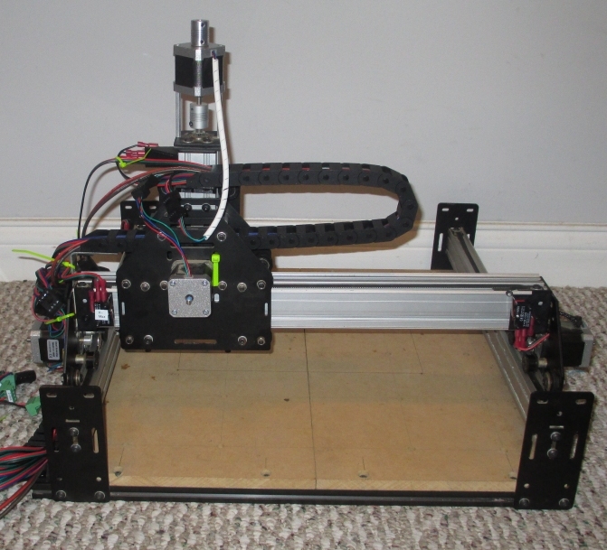
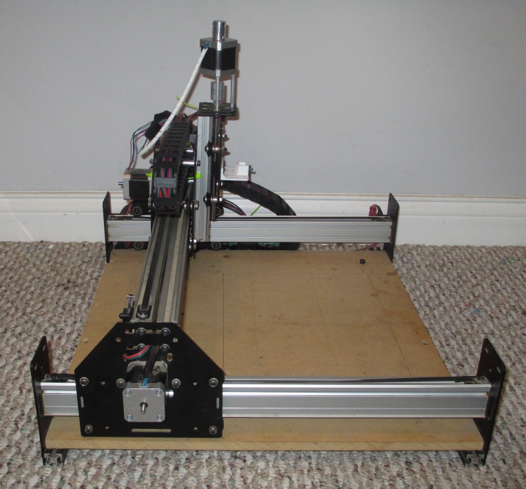
Goal 1: Shapeoko 2 Device Refurbishment
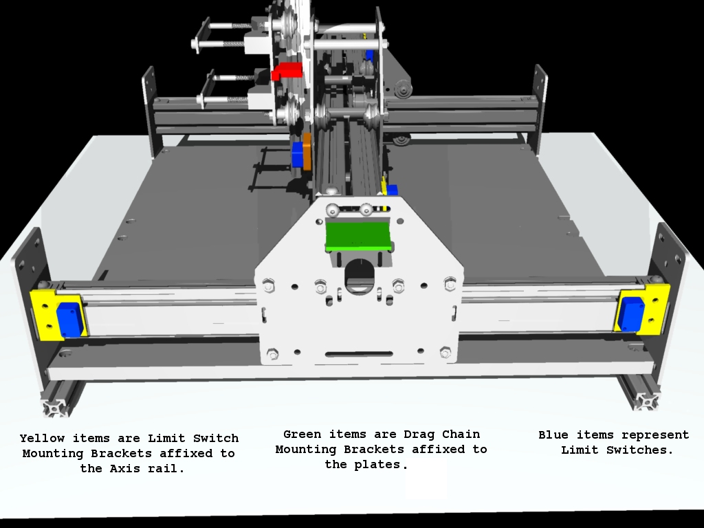
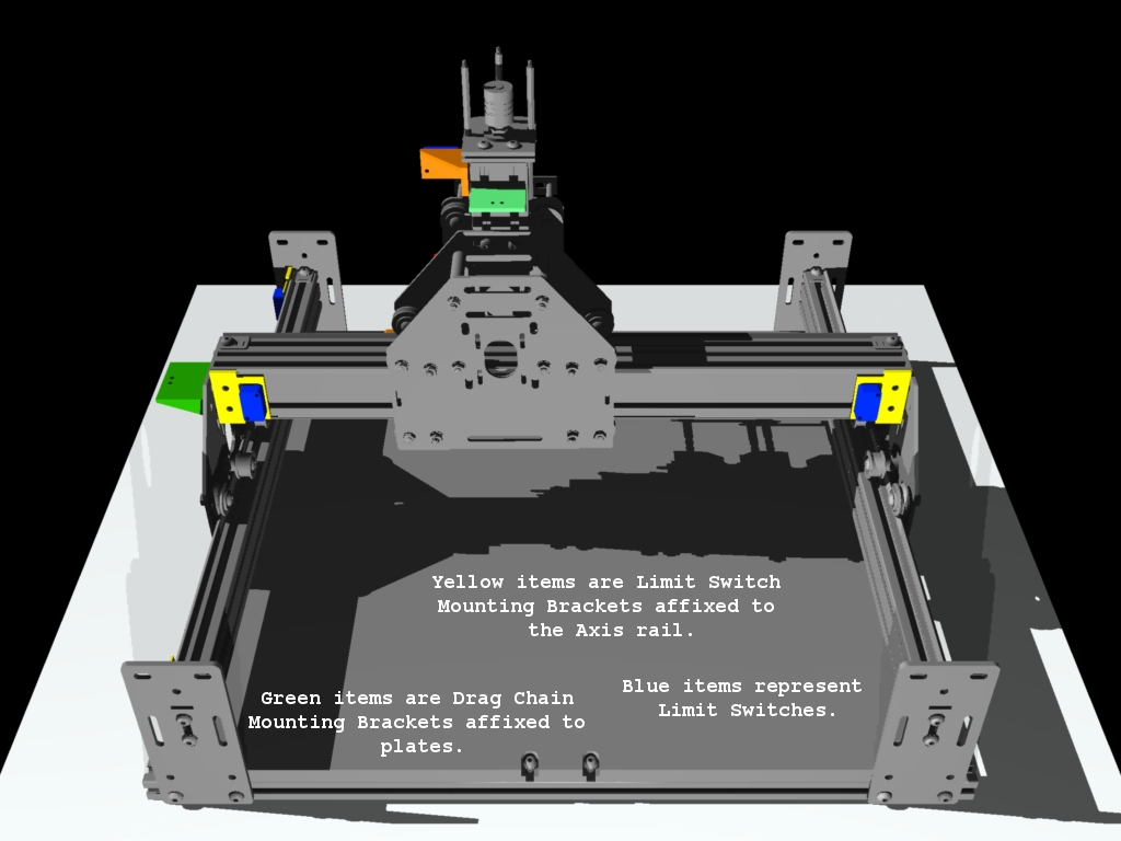
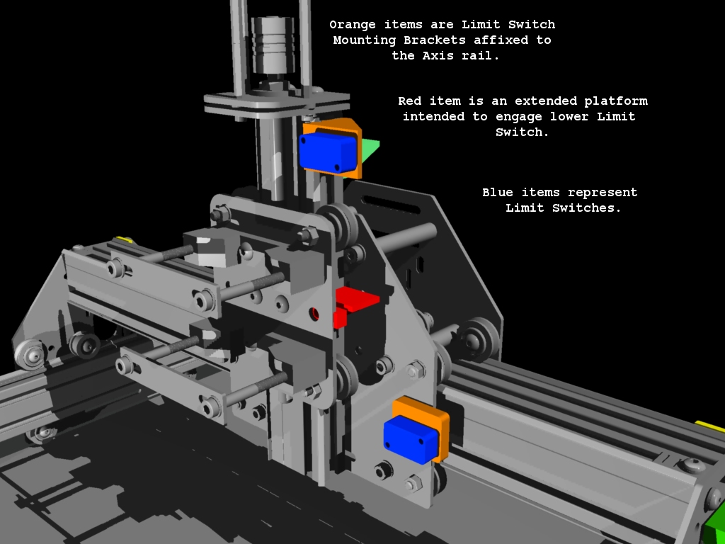
Goal 1: Placement of Custom 3D Printed Parts
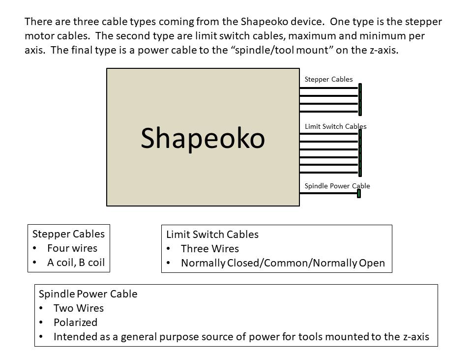
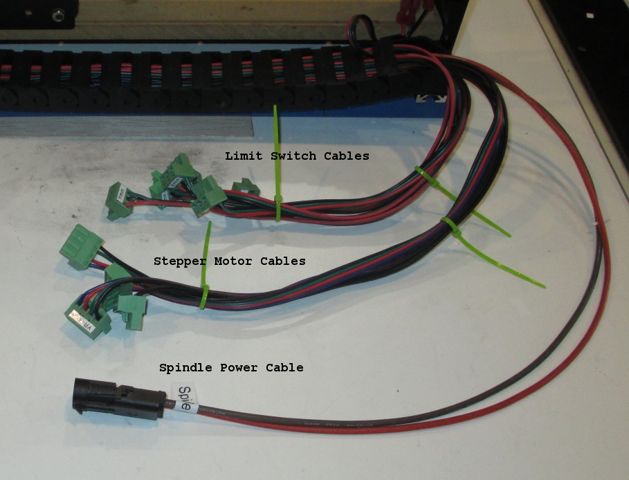
Goal 1: Rewiring
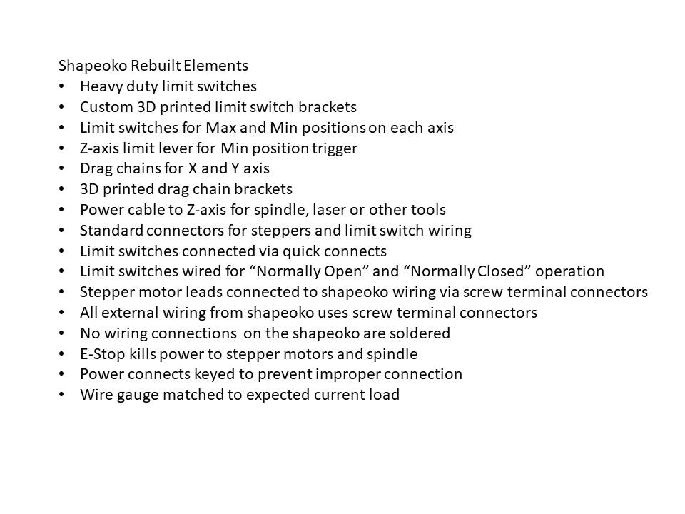
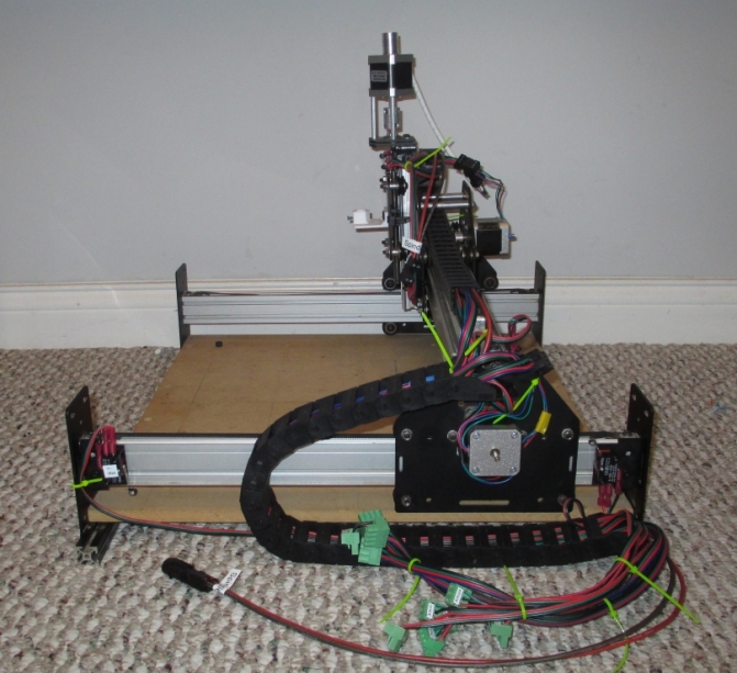
Note: The Spindle Power cable has a modification. The end connector is not common. So, a new connector has be added as a matched pair with screw terminal. The use of screw terminal connectors makes "cutting" of wiring less likely and allows reuse of connectors. The connectors do not require soldering and allow for rewiring without need to "get" new connectors or "solder" lines. A lot of wiring repairs have inline splices that cause later difficulties. The screw terminals would allow entire wiring replacement.
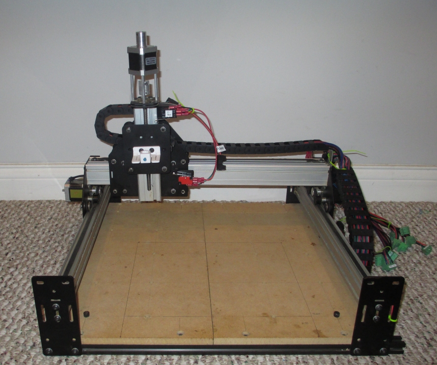
Goal 1: Completion
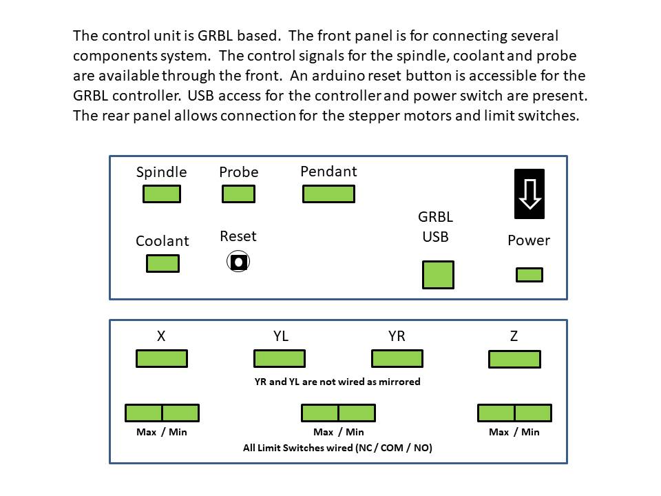
Goal 2: Controller System
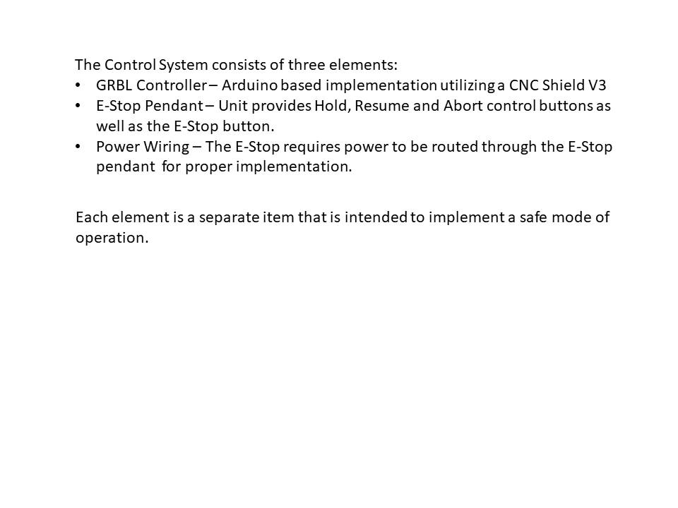
Goal 2: Controller Description
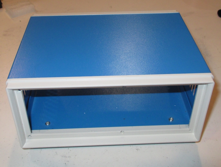
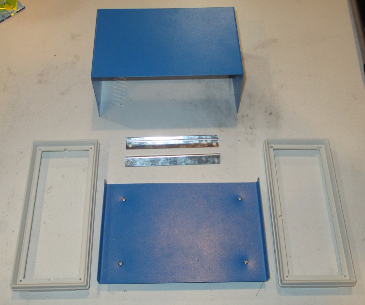
Goal 2: Controller Box
Controller Box Assembled
Controller Box Disassembled
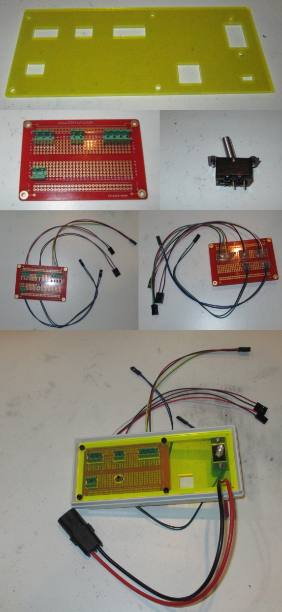
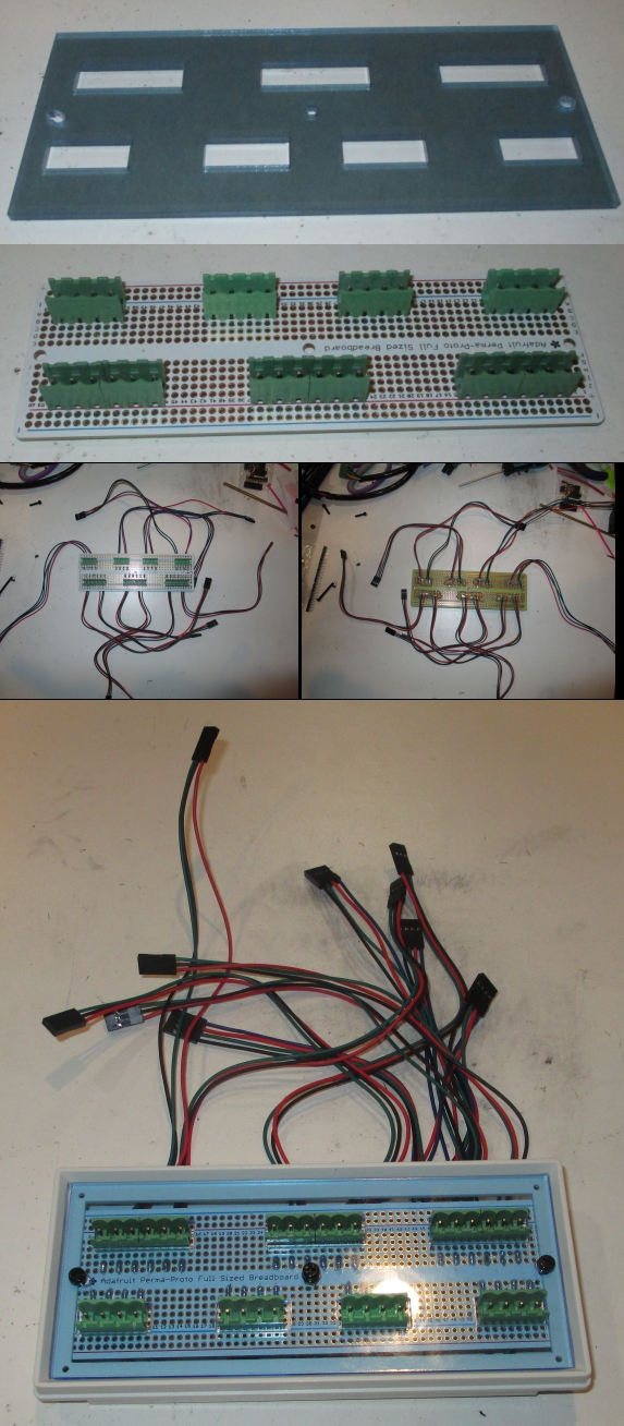
Goal 2: Front Panel Build
Goal 2: Rear Panel Build
Goal 2: Electronics
Three Boards - Arduino Uno, Arduino Prototyping Shield, CNC Shield V3.0
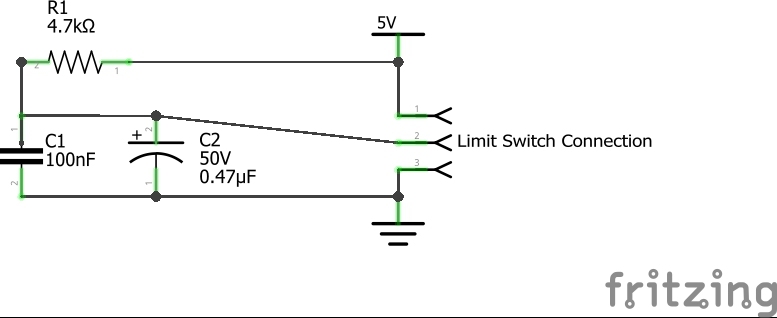
Notes: The Arduino has its power jack removed. The Arduino is powered thru the USB. The circuitry on the Prototyping Shield added noise filtering and debounce protection to the Limit Switch Lines and Control Buttons on the E-Stop pendant. The circuitry in the photo was modified according to the schematic below to improve debounce behavior.
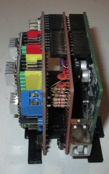
The electronic were assembled in the stack below.
Goal 2: Controller Box Assembly
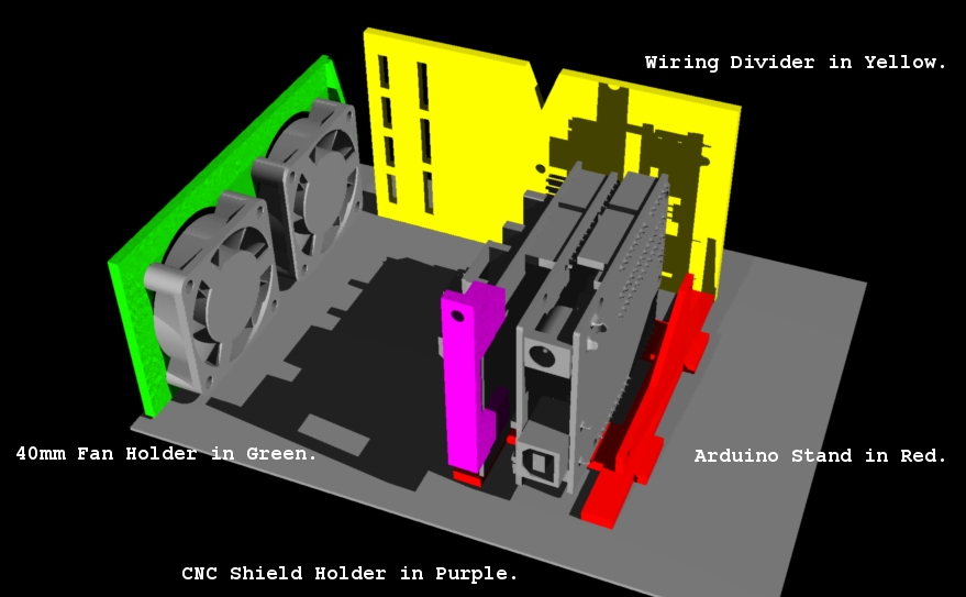
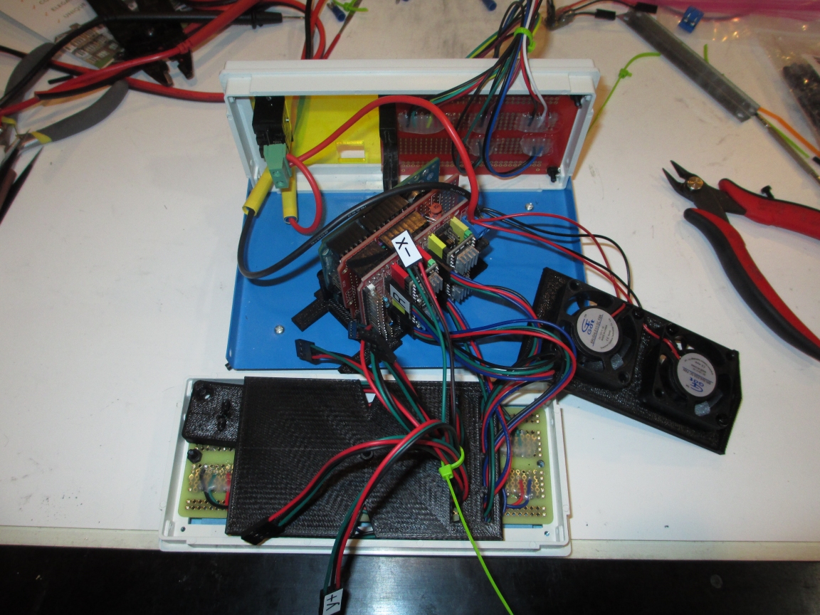
The electronic, wiring and cooling fans were organized and supported by custom 3D printed parts.
Overall Controller Box Contents
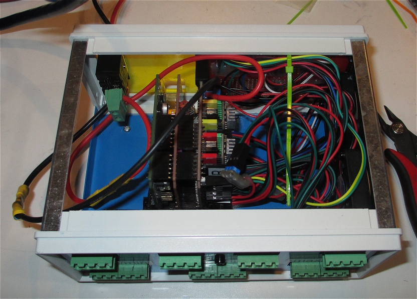
Assembled Controller Box Contents
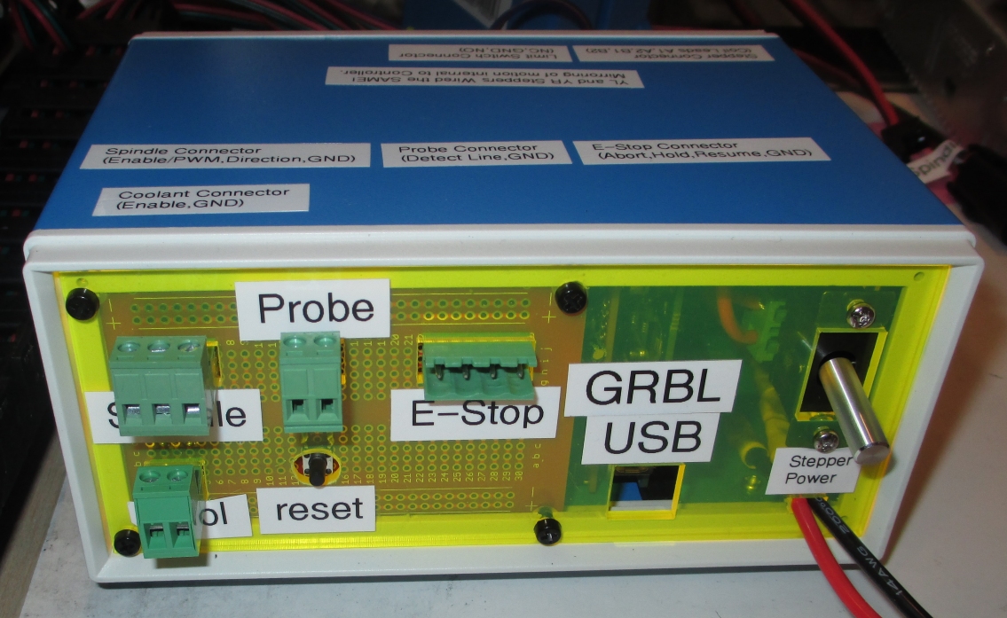
GRBL Controller Assembled and Labelled
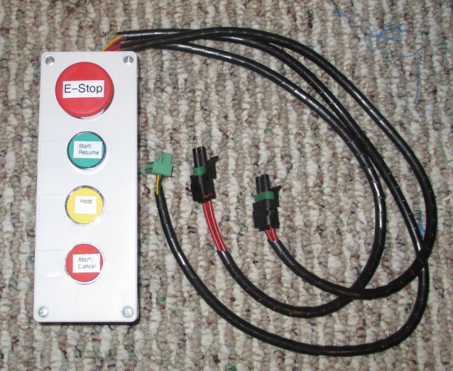
Goal 2: E-Stop pendant
Actual E-Stop pendant
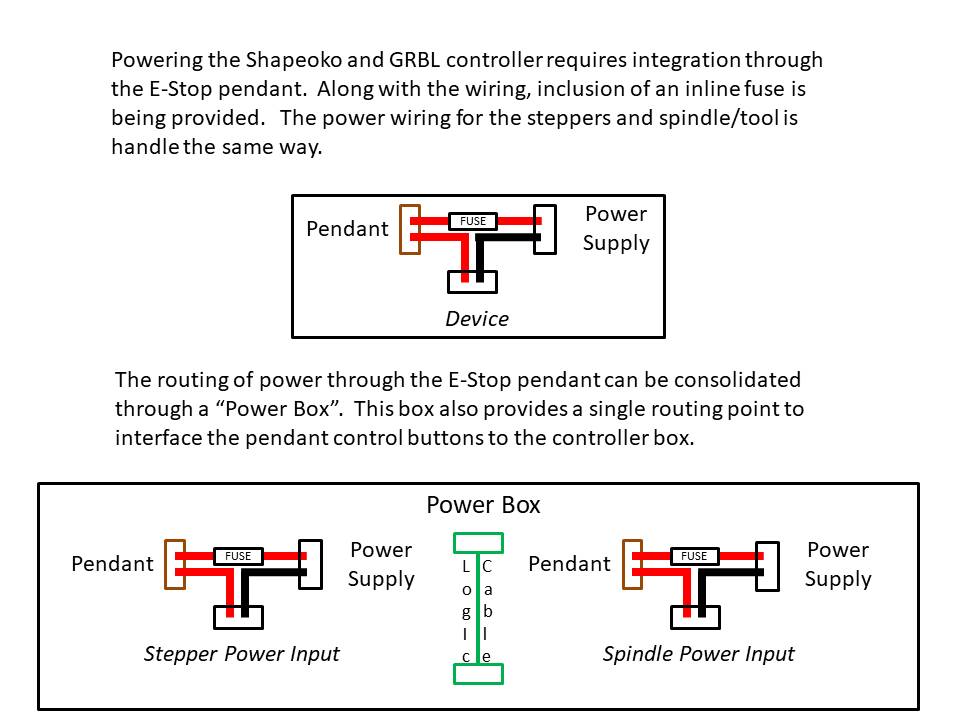
Goal 2: Power Box
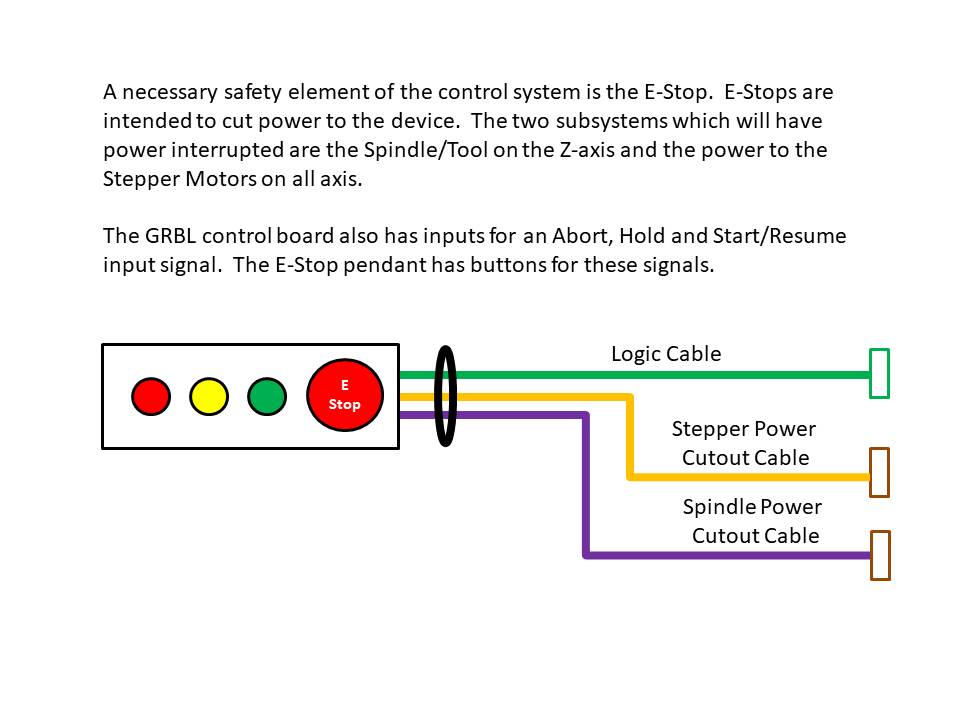
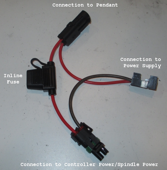
Example of an isolated power wiring harness
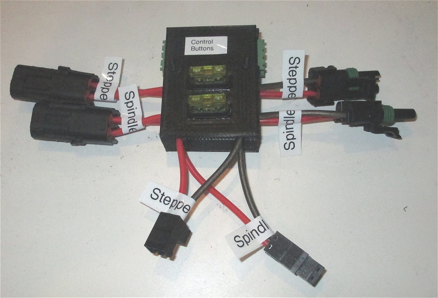
Power Box with two power wiring harnesses and control button connector
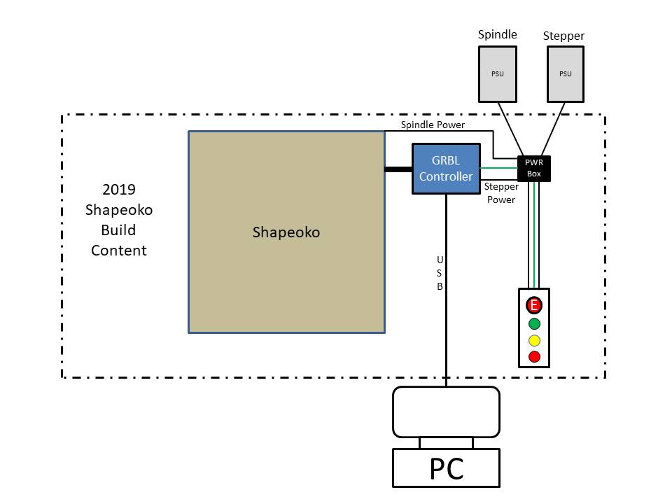
General Layout of Refurbished Shapeoko 2 and GRBL Controller
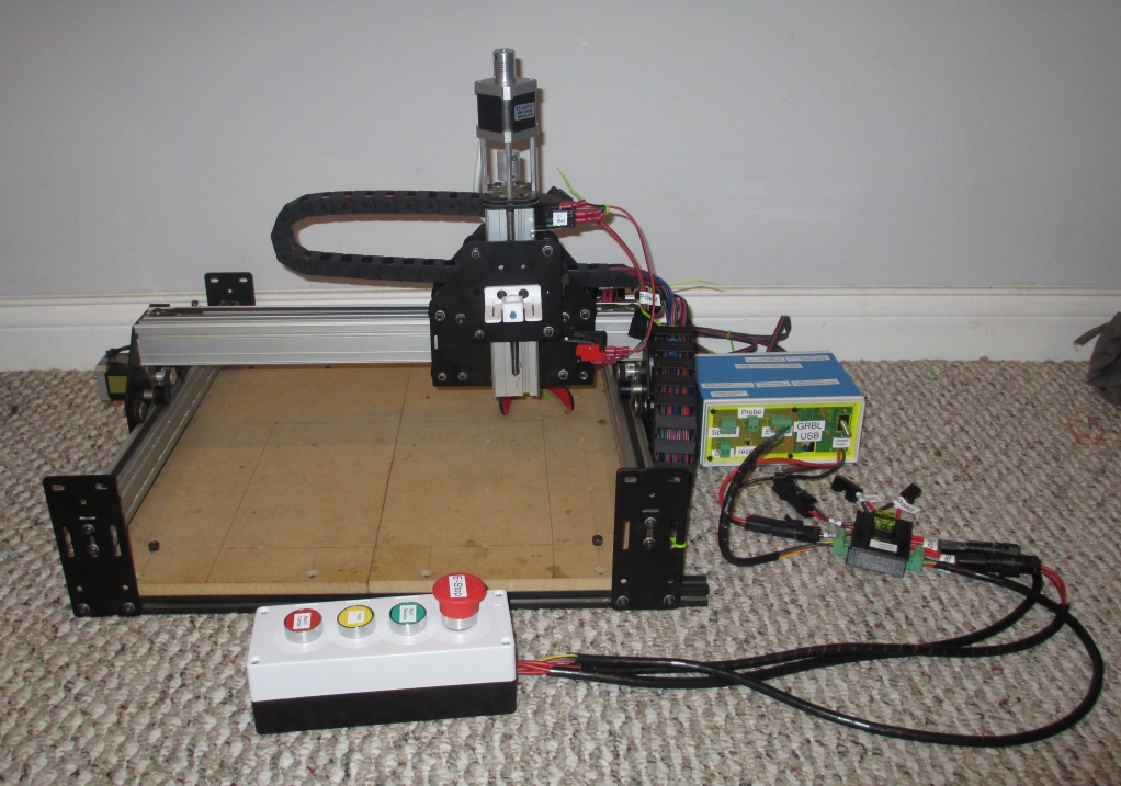
Actual Layout
