2019 Shapeoko 2 Refurbishment
General Information
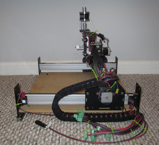
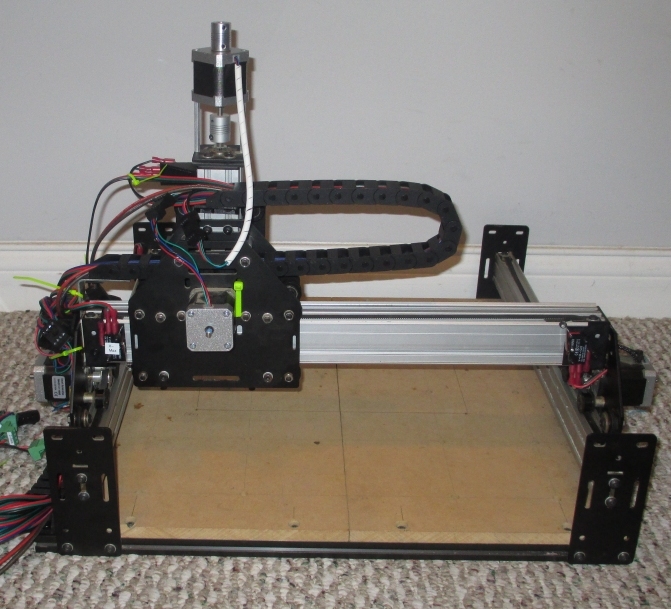
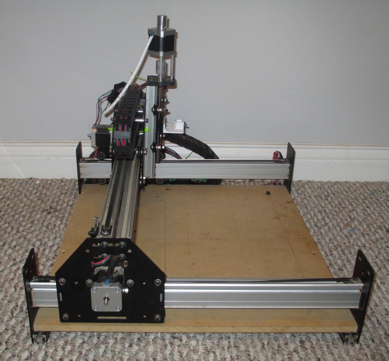
Goal 1: Shapeoko 2 Device Refurbishment
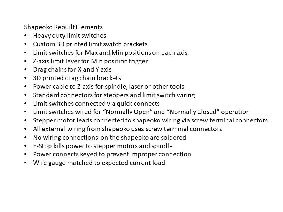
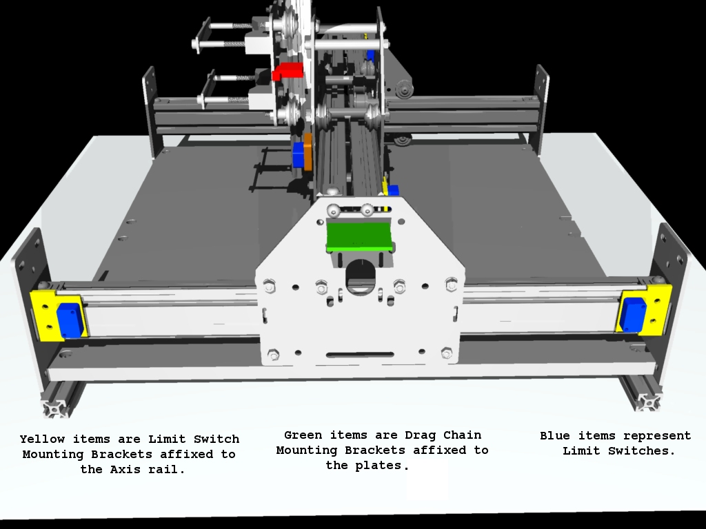
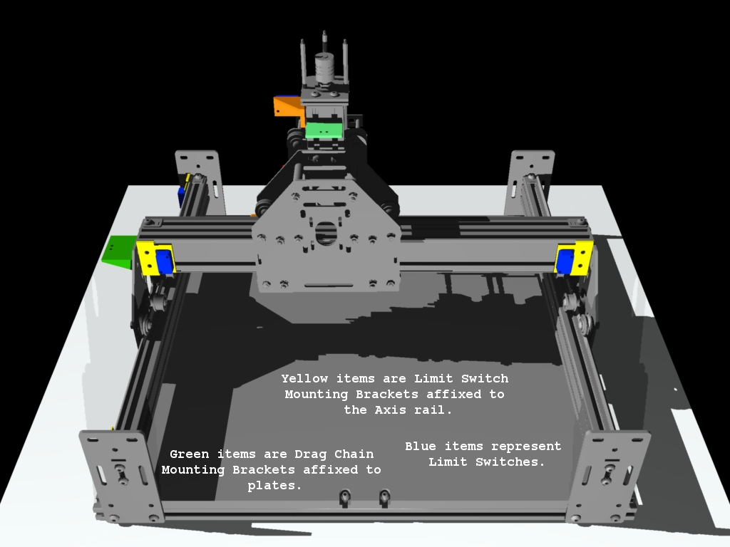
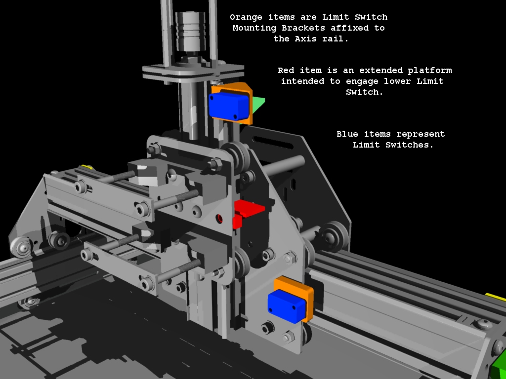
Goal 1: Placement of Custom 3D Printed Parts
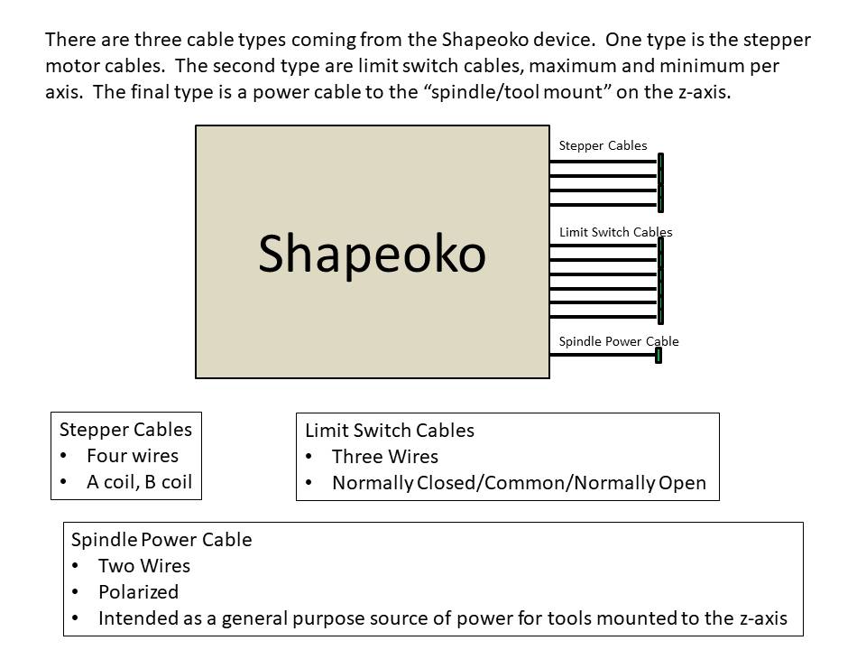
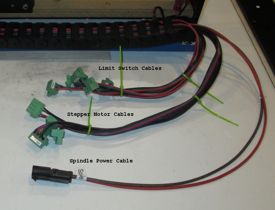
Goal 1: Rewiring
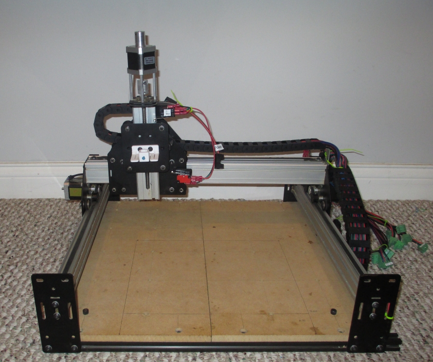
Goal 1: Completion
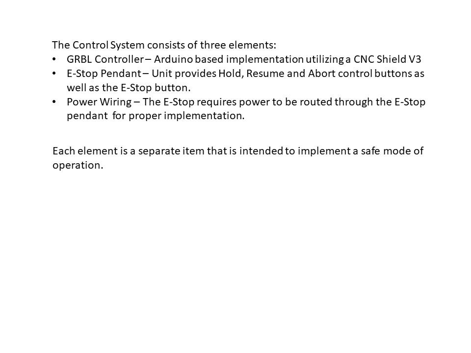
Goal 2: Controller System
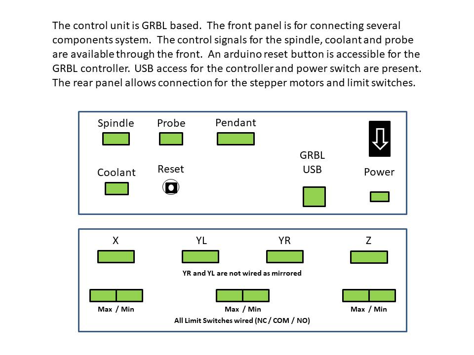
Goal 2: Controller Description
Goal 2: Controller Box
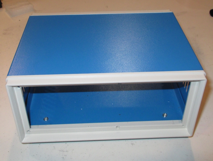
Controller Box Assembled
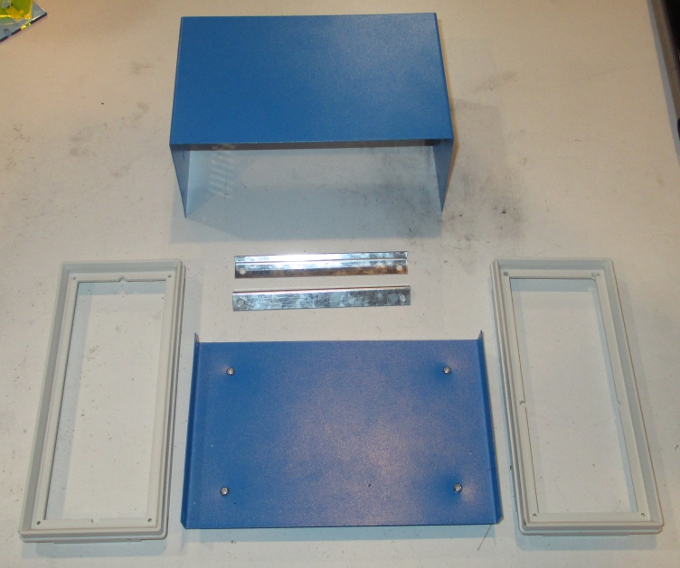
Controller Box Disassembled
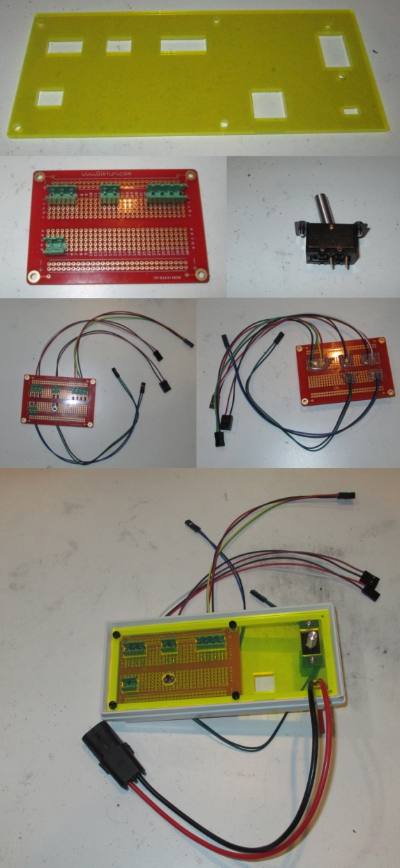
Goal 2: Front Panel Build
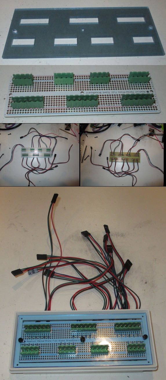
Goal 2: Rear Panel Build
Goal 2: Electronics
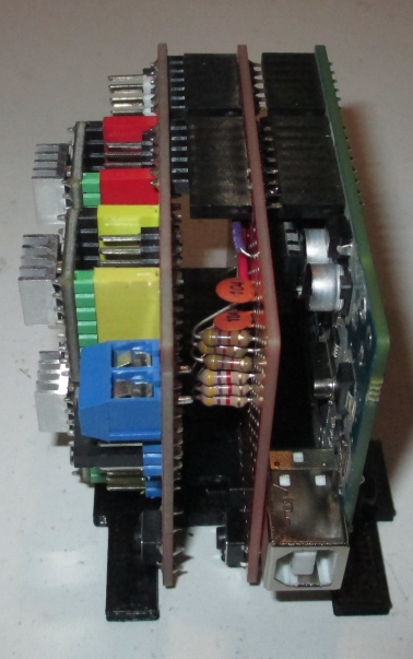
Three Boards - Arduino Uno, Arduino Prototyping Shield, CNC Shield V3.0
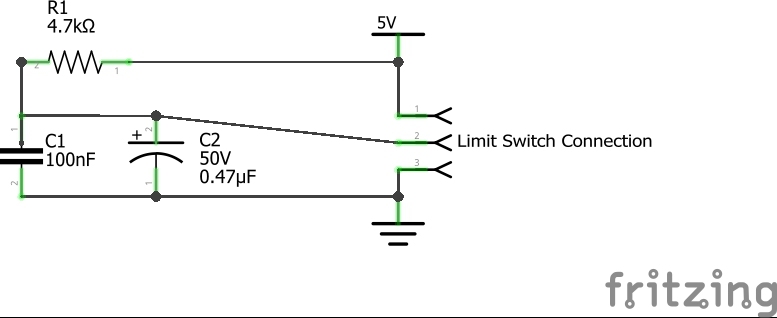
Notes: The Arduino has its power jack removed. The Arduino is powered thru the USB. The circuitry on the Prototyping Shield added noise filtering and debounce protection to the Limit Switch Lines and Control Buttons on the E-Stop pendant. The circuitry in the photo was modified according to the schematic below to improve debounce behavior.
The electronic were assembled in the stack below.
Goal 2: Controller Box Assembly
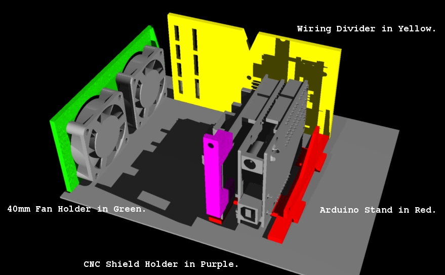
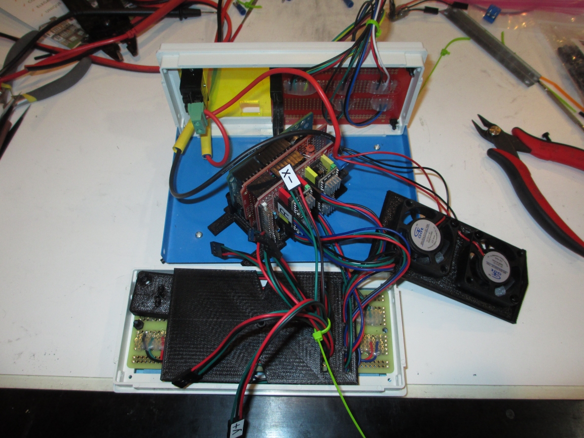
The electronic, wiring and cooling fans were organized and supported by custom 3D printed parts.
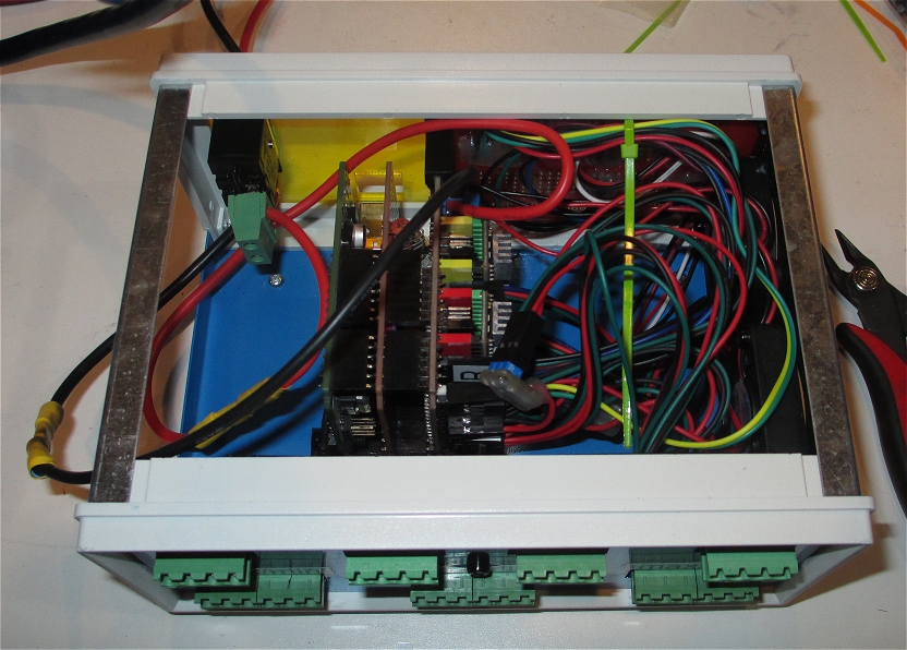
Overall Controller Box Contents
Assembled Controller Box Contents
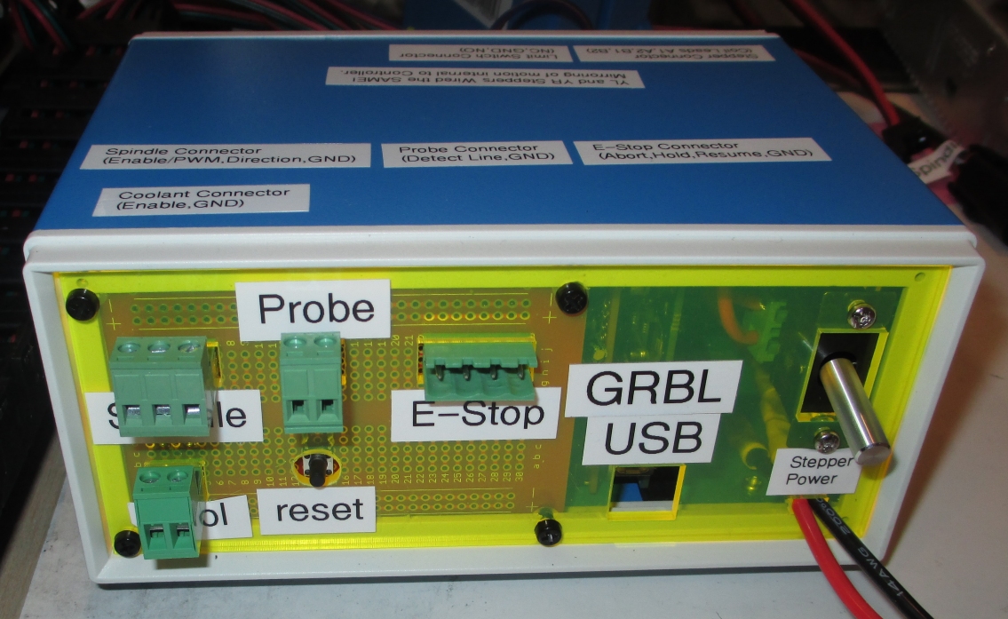
GRBL Controller Assembled and Labelled
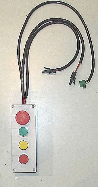
Goal 2: E-Stop pendant
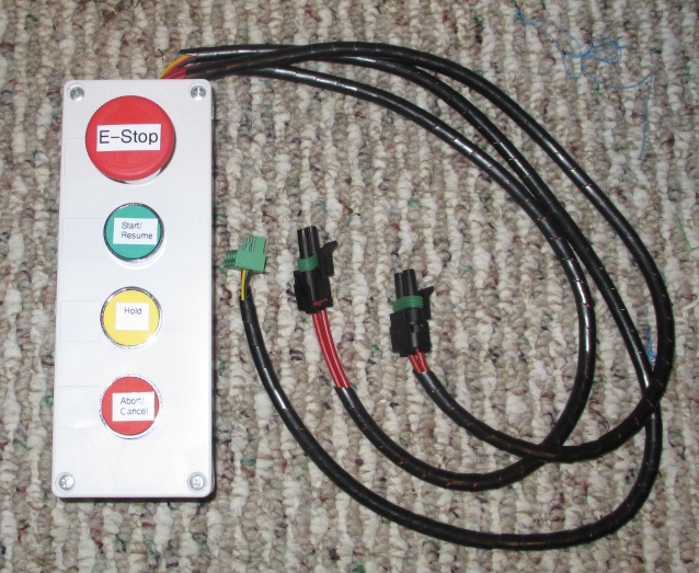
Actual E-Stop pendant
General Photos
E-Stop Pendant
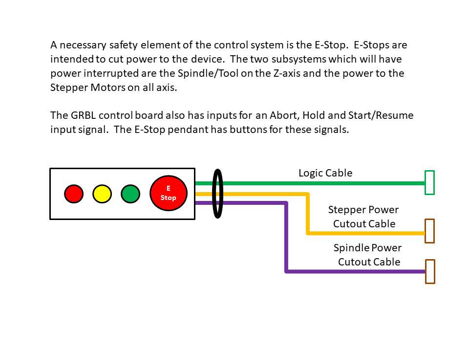
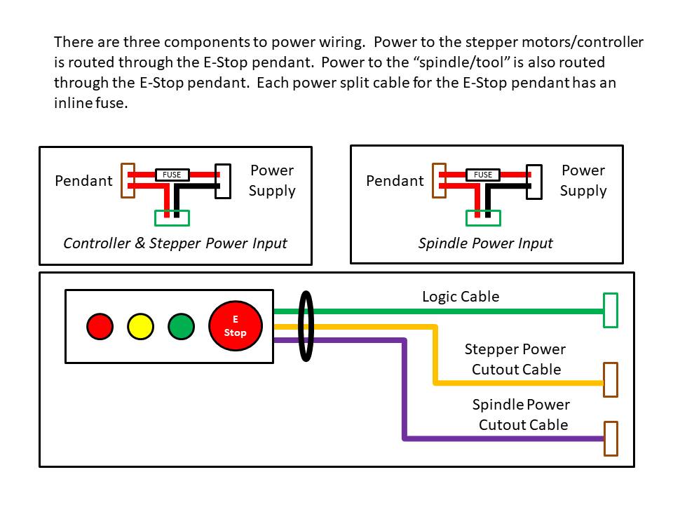
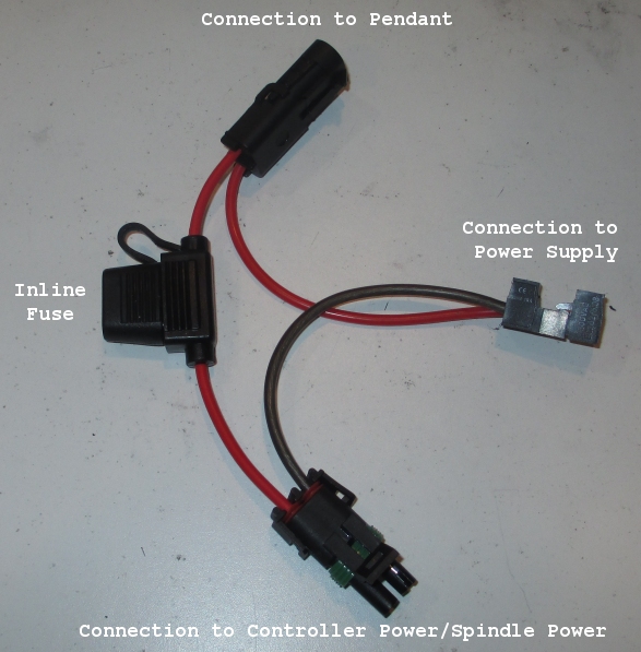
E-Stop Pendant Power Cutoff Wiring
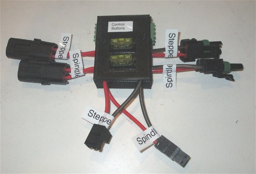
Power Box
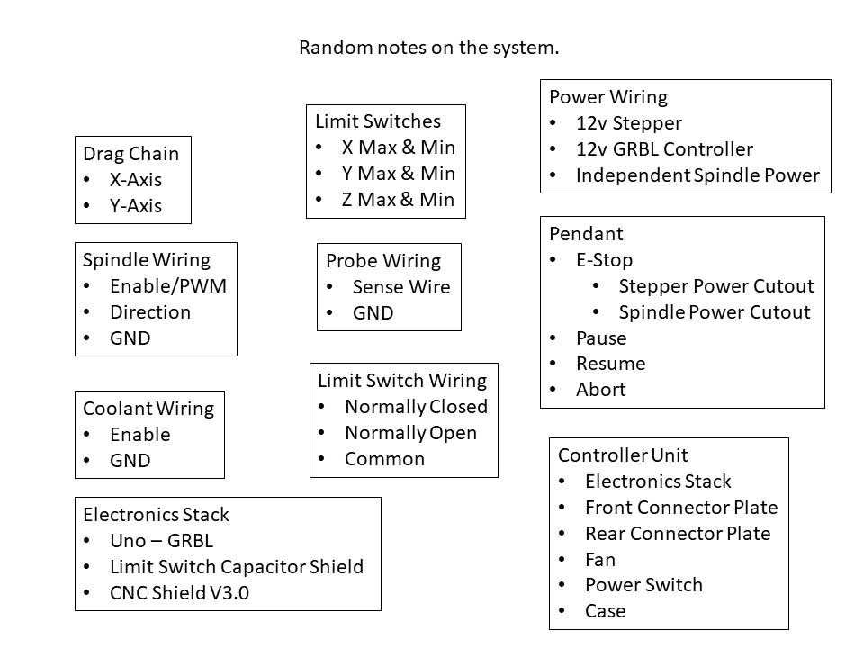
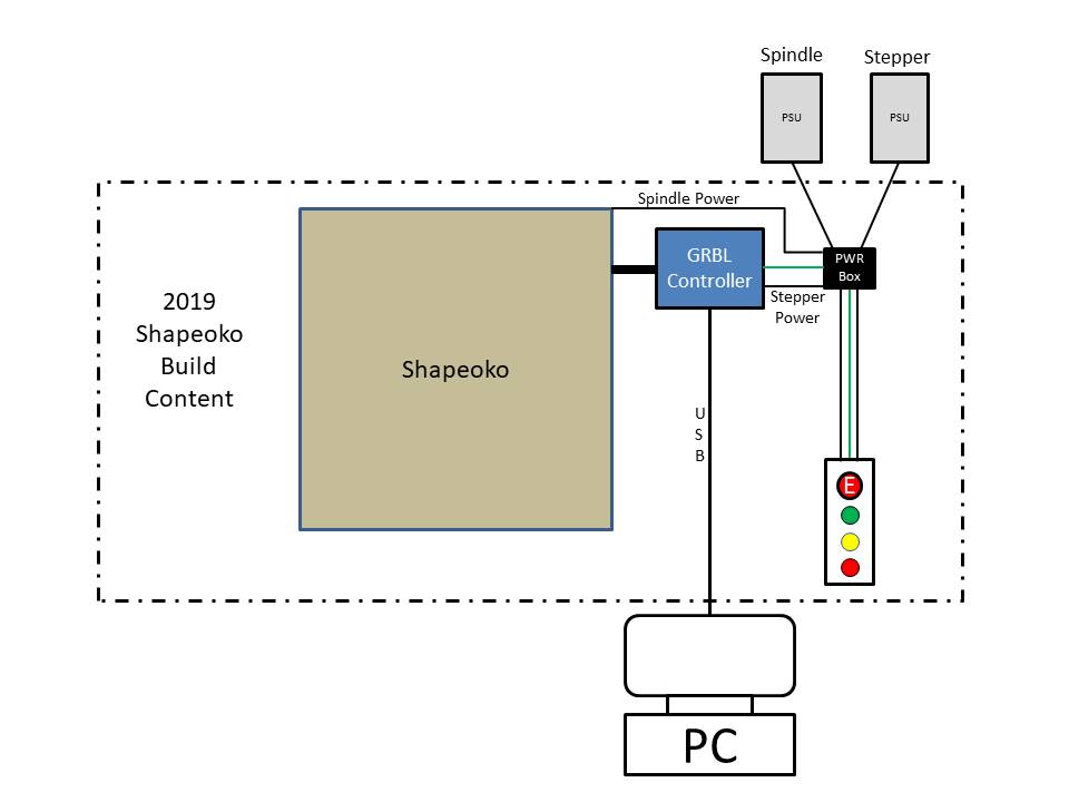
General Layout
