Difference between revisions of "LCEM"
| Line 63: | Line 63: | ||
====Madness Indicator==== | ====Madness Indicator==== | ||
| − | Some may notice the old/ancient resistors being used. These | + | Some may notice the old/ancient resistors being used. These were part of a donation from a member, now deceased, with an electrical engineering degree older then almost all of LVL1's members. Ron, you are missed. |
===Simple Presentation=== | ===Simple Presentation=== | ||
| + | |||
| + | The obvious black RadioShack project box with two LEDs on top design was discarded immediately. LVL1 is about building distinctive things when something less is required. The design chosen would be too much work with multiple intents. The design would have its schematic visible for those curious to know how it worked. The design would have its PCB visible to show how the PCB and schematic are not physically laid out the same. Laser cut acrylic would be used since this is a laser cutter project. And because the author likes dry erase boards, a dry erase marker most have some fundamental part in the build. | ||
| + | |||
| + | Here is what was decided. | ||
| + | |||
| + | [[File:Laser Cutter Enable Etching Plate Not Mirrored.jpg]] | ||
| + | |||
| + | Above is the file to be used to create the PCB/Mounting Plate/Educational Schematic/Acrylic thing. | ||
| + | |||
| + | ====Madness Indicator==== | ||
| + | All of the above. | ||
Revision as of 15:38, 31 May 2015
LASER CUTTER ENABLED MODULE or LVL1 versus The Smoke Monster
Contents
The Genesis
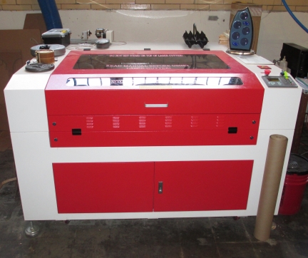
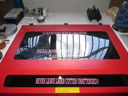
The LVL1 Hackerspace has had the great fortune of receiving a grant to purchase, among other things, a large format laser cutter.
The Problems
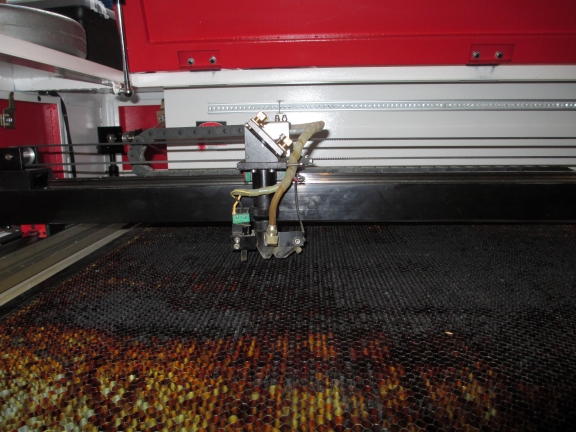
But with a laser cutter comes the responsibility of handling the fumes (The Smoke Monster). A simple examination of the cutting bed shows its ilk.
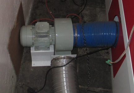
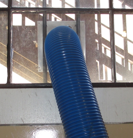
The first method of attack was to vent the beast.
But fumes vented to the outside, still smell funny. And even though LVL1 is located near a place that turns pigs into wonderful breakfast meats, there were a few complaints. LVL1 dutifully upgraded the system with a larger capacity filter and all went well.
But filters are a fussy lot and when they clog, the smoke monster escapes. After much coughing, a new element is added that monitors the air flow through the filter and when reduced or clogged, the laser firing circuit is disabled.
All is now right with the world, unless you are using the laser cutter and the filter trips the flow switch and the laser circuit stops firing the laser. The cause of laser-interruptus is not always apparent. Sometimes the settings on the machine can prevent the laser from firing during etching operations. The top closed switch could stop the firing. Both cases result in the laser cutter gracefully moving across your material while nothing is vaporized. So how do you know its the filter flow switch and not something else?
A Laser Cutter Enabled Module.
The requirements were simple.
1. Show a light when the laser circuit is enabled or conversely when disabled.
This makes sense. Then someone asked about what if the indicator system is not working. A lack of light could mean what it is supposed to mean or the indicator is not working.
2. Show a light in either case. Green for enabled and Red for disabled. No light means the indicator circuit is not working. A bi-color LED would solve the problem.
Problem solved. Until someone asked about color blindness and knowing if the LED is RED or Green. This was an excellent point.
3. Two LEDs are used. One Green with appropriate label of "Enabled" and one Red with appropriate label of "Disabled".
The crowd then remarked about statistics keeping, quantitative measures and raspberry pi. These wonderful suggestions were immediately suppressed and work on the indicator began.
All On Paper.
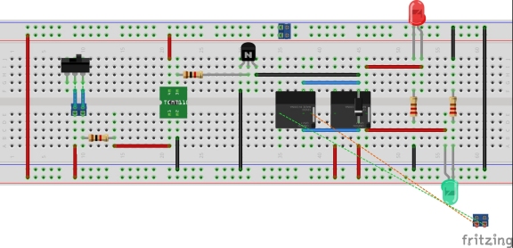
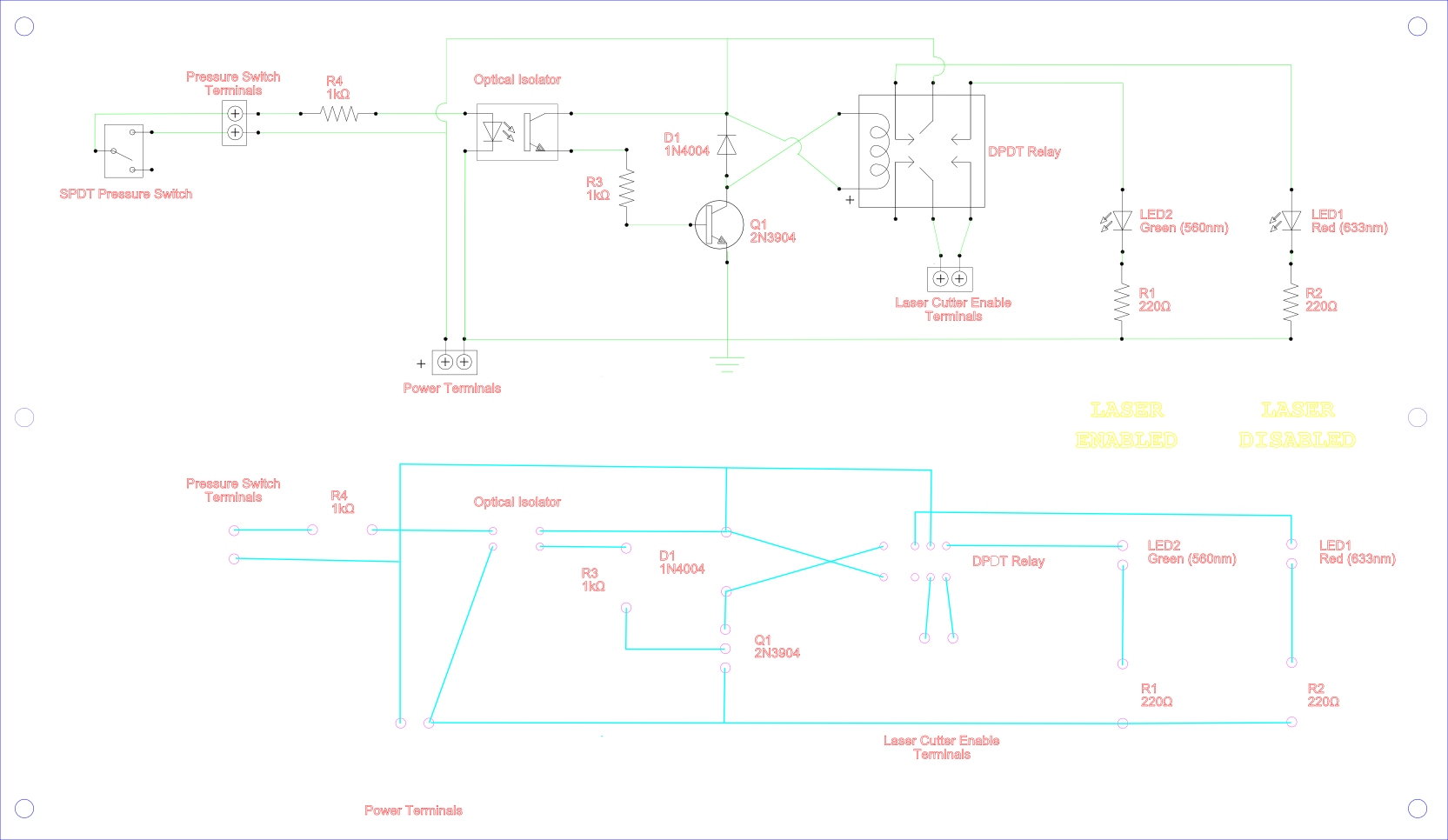
The preliminary design began. These documents were produced.
The design is simple. The filter flow switch is connected to power and an optical coupler. When the flow is adequate, the optical coupler is activated with a small voltage effectively using the flow switch as a simple off-on switch for its embedded LED. The other side of the optical coupler is used to switch on a relay. When the relay is inactive, power is supplied to a Red LED. When the relay is active, power is supplied to a Green LED instead. Green LED lit means laser circuit enabled while Red LED lit means laser circuit is disabled. If not LEDs are lit then the indication system is not working.
Madness Indicator
Use of an optical coupler is a bit over kill. LVL1 Hackerspace never criticizes the overkill.
In Real Life
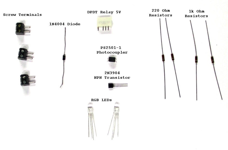
The preliminary design was sound. It was time to gather components. Real life meant that a single DPDT relay could be used instead of two SPDT relays with tied together coils. Real relays can also have polarized coil inputs to accommodate a number of real world issues. LEDs, one Green and one Red should be the easiest things to come by. But the easiest things to come by are often not readily at hand when going through a hackerspace component junk drawer. That is not to say that we didn't find a Green and a Red LED, but the ones found did not aesthetically match one another. Then the issue of brightness came into the discussion. The solution was within the madness quotient of the builders and two bright RGB LEDs were selected. The selection of the back-emf diode was based upon a 1N4004 being in the junk drawer. Quick resistor values were chosen and pulled from junk drawer.
Madness Indicator
Some may notice the old/ancient resistors being used. These were part of a donation from a member, now deceased, with an electrical engineering degree older then almost all of LVL1's members. Ron, you are missed.
Simple Presentation
The obvious black RadioShack project box with two LEDs on top design was discarded immediately. LVL1 is about building distinctive things when something less is required. The design chosen would be too much work with multiple intents. The design would have its schematic visible for those curious to know how it worked. The design would have its PCB visible to show how the PCB and schematic are not physically laid out the same. Laser cut acrylic would be used since this is a laser cutter project. And because the author likes dry erase boards, a dry erase marker most have some fundamental part in the build.
Here is what was decided.
Above is the file to be used to create the PCB/Mounting Plate/Educational Schematic/Acrylic thing.
Madness Indicator
All of the above.
