|
|
| Line 931: |
Line 931: |
| | ---- | | ---- |
| | | | |
| − | == Parts List ==
| |
| − |
| |
| − |
| |
| − | {|class="wikitable"
| |
| − | !colspan="4"|ATTINY85 TOKEN/NEOPIXEL CONTROLLER/TONE CONTROLLER PARTS
| |
| − | |-
| |
| − | |Device
| |
| − | |Name
| |
| − | |-
| |
| − | |[[File:JAC_MED_MON_ATTINY85.jpg|left|thumbnail|x200px]]
| |
| − | |* ATTiny85
| |
| − | |[[File:JAC_MED_MON_TACTILE_SWITCH.jpg|left|thumbnail|x200px]]
| |
| − | |* Tactile Momentary Switch
| |
| − | |-
| |
| − | |
| |
| − | [[File:JAC MED MON ATTINY85 TOKEN BOX PARTS.jpg|thumb]]
| |
| − | | * Enclosure Parts
| |
| − | |}
| |
| − |
| |
| − | {|class="wikitable"
| |
| − | !colspan="4"|EXTERNAL UNIT PARTS
| |
| − | |-
| |
| − | |Device
| |
| − | |Name
| |
| − | |-
| |
| − | |[[File:JAC MED MON TMP36 SENSOR.jpg|left|thumbnail|x200px]]
| |
| − | |* TMP36 Temperature Sensor
| |
| − | |[[File:JAC MED MON PULSE SENSOR.jpg|left|thumbnail|x200px]]
| |
| − | |* IR Pulse Sensor with incorrect Labelling (Qty. 2)
| |
| − | |-
| |
| − | |
| |
| − | [[File:JAC MED MON BNO055 PART.jpg|left|thumbnail|x200px]]
| |
| − | |
| |
| − | [[File:JAC MED MON NEOPIXEL PART.jpg|left|thumbnail|x200px]]
| |
| − | |
| |
| − | [[File:JAC MED MON MPU6050 PART.jpg|left|thumbnail|x200px]]
| |
| − | |
| |
| − | [[File:JAC MED MON PCF8574 PART.jpg|left|thumbnail|x200px]]
| |
| − | |
| |
| − | [[File:JAC MED MON PIEZO PART.jpg|left|thumbnail|x200px]]
| |
| − | |
| |
| − | [[File:JAC MED MON TCA9548A PART.jpg|left|thumbnail|x200px]]
| |
| − | |
| |
| − | [[File:JAC MED MON TCRT5000 PART.jpg|left|thumbnail|x200px]]
| |
| − | |
| |
| − | [[File:JAC MED MON LED PART.jpg|left|thumbnail|x200px]]
| |
| − | |
| |
| − | [[File:JAC MED MON MOMENTARY SWITCH PART.jpg|left|thumbnail|x200px]]
| |
| − | |
| |
| − | [[File:JAC MED MON ROTARY ENCODER PART.jpg|left|thumbnail|x200px]]
| |
| − | |
| |
| − | [[File:JAC MED MON VIBRATING MOTOR PART.jpg|left|thumbnail|x200px]]
| |
| − | |
| |
| − | [[File:JAC MED MON PROTOTYPE SHIELD PART.jpg|left|thumbnail|x200px]]
| |
| − | |
| |
| − | [[File:JAC_MED_MON_CONTROL_PANEL_BRACKETS.jpg|left|thumbnail|x200px]]
| |
| − | |
| |
| − | [[File:JAC_MED_MON_PORT_MOUNTING_BRACKETS.jpg|left|thumbnail|x200px]]
| |
| − | |}
| |
| | | | |
| | === 3D Print Elements === | | === 3D Print Elements === |
Revision as of 17:24, 11 December 2021
This Amazing, Affordable, Earth Changing Device, for which no endorsement is to be inferred, is designed as a collection of layers.
Main Unit Sensor Layer
Components
| General Components
|
| Device
|
Name
|
Use
|
|
|
Arduino DUE Prototyping Shield
|
Base PCB for layer
|
|
|
* 160x128 LCD TFT SPI 1.8" Module with SD Socket (Heyaodz111208)
|
Display and SD Card Socket
|
|
|
Headers
|
Divided into various length for mounting sensors and other devices
|
Sensors
| Sensors
|
| Device
|
Name
|
Description
|
Interface
|
|
|
AMG8833 Thermal Imager Sensor (TinyCircuits)
|
8x8 thermal image sensor
|
I2C Address 0x69
|
|
|
Capacitive Touch Fingerprint Scanner (DFROBOT)
|
ID809 high-performance processor and semiconductor fingerprint sensor
|
Serial UART
|
|
|
MAX30102 Pulse and O2 Saturation Sensor (MH-ET Live)
|
IR and Visible Pulse and O2 Saturation Measurement
|
I2C Address 0x57
|
|
|
MLX90614 Contactless Temperature Sensor
|
Field and object temperature sensor
|
I2C Address 0x5A
|
|
|
VL53L0X TOF Laser Distance Sensor (Onyehn)
|
IR Laser time of flight distance sensor
|
I2C Address 0x29
|
Shield Wiring
|
|
|
|
| Pin Mapping
|
| Due Shield Pin
|
Function
|
MLX90614
|
AMG8833
|
VL53L0X
|
MAX30102
|
FP Scan
|
TFT
|
SD Socket
|
Control Panel
|
Analog Test Socket
|
| 2
|
Interrupt
|
|
|
|
|
|
|
|
INT
|
|
| 3
|
Interrupt
|
|
|
|
|
IRQ
|
|
|
|
|
| 4
|
Interrupt
|
|
|
|
INT
|
|
|
|
|
|
| 5
|
Interrupt
|
|
INT
|
|
|
|
|
|
|
| 6
|
Digital I/O
|
|
|
GPIO1
|
|
|
|
|
|
|
| 7
|
Digital I/O
|
|
|
XSHUT
|
|
|
|
|
|
|
| 8
|
Digital I/O
|
|
|
|
|
|
|
SD_CS
|
|
|
| 9
|
Digital I/O
|
|
|
|
|
|
RST
|
|
|
|
| 10
|
Digital I/O
|
|
|
|
|
|
CS
|
|
|
|
| 11
|
Digital I/O
|
|
|
|
|
|
AO
|
|
|
|
| 18
|
TX_1
|
|
|
|
|
RX
|
|
|
|
|
| 19
|
RX_1
|
|
|
|
|
TX
|
|
|
|
|
| 20
|
SDA
|
SDA
|
SDA
|
SDA
|
SDA
|
|
|
|
SDA
|
|
| 21
|
SCL
|
SCL
|
SCL
|
SCL
|
SCL
|
|
|
|
SCL
|
|
| A0
|
|
|
|
|
|
|
|
|
|
Signal
|
| SPI
|
MISO
|
|
|
|
|
|
|
SD_MISO
|
|
|
| SPI
|
MOSI
|
|
|
|
|
|
SDA
|
SD_MOSI
|
|
|
| SPI
|
SCK
|
|
|
|
|
|
SCK
|
SD_SCK
|
|
|
|
Assembly
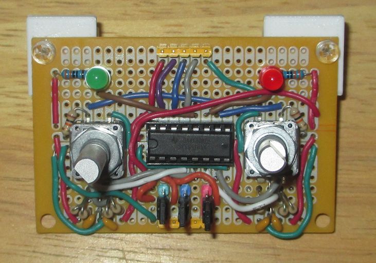
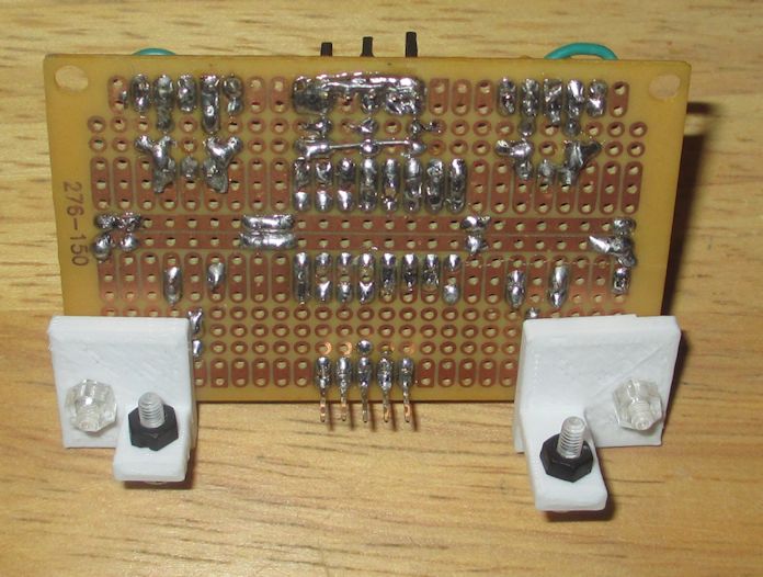
Control Panel
Components
| Control Panel Part
|
| Device
|
Name
|
Use
|
|
|
RadioShack PCB 276-150
|
Control Panel PCB
|
|
|
Header Pins (various colors)
|
Connector to Main Sensor Layer and configuration jumpers
|
|
|
Jumper/Short
|
Configure Control Panel I2C Address
|
|
|
PCF8574 Remote 8-Bit I/O Expander
|
Monitor Rotary Encoders and Set LED Condition
|
|
|
LEDs
|
Provide visual ques to user
|
|
|
Rotary Encoder
|
User interface device
|
|
|
Mounting Brackets
|
Control Panel mounting brackets to Main Sensor Layer
|
Control Panel Wiring
|
|
| Device
|
|
Schematic
|
|
|
| Pin Mapping
|
| Device
|
SIGNAL
|
DUE Shield Pin
|
Function
|
| Controls
|
Vin
|
3.3V
|
Power
|
| Controls
|
SDA
|
20
|
SDA-I2C
|
| Controls
|
SCL
|
21
|
SCL-I2C
|
| Controls
|
INT
|
2
|
GPIO
|
| Controls
|
GND
|
GND
|
Power
|
|
|
Assembly
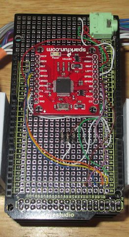
Audio Layer
Components
| General Components
|
| Device
|
Name
|
Use
|
|
|
Arduino DUE Prototyping Shield
|
Base PCB for layer
|
|
|
Breakout Board for VS1103 MIDI Decoder
|
Provide audio to user
|
|
|
Stereo Phono Jack
|
Audio output
|
Shield Wiring
|
|
|
|
| Pin Mapping
|
| Device
|
SIGNAL
|
DUE Shield Pin
|
Function
|
| VS1103
|
Vin
|
3.3V
|
Power
|
| VS1103
|
GND
|
GND
|
Power
|
| VS1103
|
TX
|
17
|
RX-Serial2
|
| VS1103
|
RX
|
16
|
TX-Serial2
|
| VS1103
|
GPIO0
|
30
|
GPIO
|
| VS1103
|
GPIO1
|
32
|
GPIO
|
| VS1103
|
RST
|
28
|
GPIO
|
| VS1103
|
DREQ
|
24
|
GPIO
|
| VS1103
|
BSYNC
|
26
|
GPIO
|
| VS1103
|
CS
|
22
|
GPIO
|
| VS1103
|
SO
|
SPI-HDR
|
MISO
|
| VS1103
|
SI
|
SPI-HDR
|
MOSI
|
| VS1103
|
SCLK
|
SPI-HDR
|
SCK
|
|
Assembly
Ports Layer
Components
| General Components
|
| Device
|
Name
|
Use
|
|
|
Arduino DUE Prototyping Shield
|
Base PCB for layer
|
|
|
TCA9548A 1-to-8 I2C Multiplexer Breakout
|
- Provide separate I2C bus isolation for each port
- I2C Address 0x1E
|
|
|
Dual RJ45 Port Box
|
Provide External Unit connectivity to device
|
Shield Wiring
|
|
| Device
|
|
Notes
|
|
|
| Pin Mapping
|
| Port #
|
Line #
|
DUE Shield Pin
|
Function
|
|
Port #
|
Line #
|
DUE Shield Pin
|
Function
|
|
Port #
|
Line #
|
DUE Shield Pin
|
Function
|
|
Port #
|
Line #
|
DUE Shield Pin
|
Function
|
| 0
|
1
|
3.3V
|
Power
|
|
1
|
1
|
3.3V
|
Power
|
|
2
|
1
|
3.3V
|
Power
|
|
3
|
1
|
3.3V
|
Power
|
| 0
|
2
|
GND
|
Power
|
|
1
|
2
|
GND
|
Power
|
|
2
|
2
|
GND
|
Power
|
|
3
|
2
|
GND
|
Power
|
| 0
|
3
|
|
MUX-SD0
|
|
1
|
3
|
|
MUX-SD1
|
|
2
|
3
|
|
MUX-SD2
|
|
3
|
3
|
|
MUX-SD3
|
| 0
|
4
|
|
MUX-SC0
|
|
1
|
4
|
|
MUX-SC1
|
|
2
|
4
|
|
MUX-SC2
|
|
3
|
4
|
|
MUX-SC3
|
| 0
|
5
|
53
|
GPIO0
|
|
1
|
5
|
27
|
GPIO0
|
|
2
|
5
|
A10/64
|
Analog0
|
|
3
|
5
|
A5/59
|
Analog0
|
| 0
|
6
|
51
|
GPIO1
|
|
1
|
6
|
29
|
GPIO1
|
|
2
|
6
|
A9/63
|
Analog1
|
|
3
|
6
|
A4/58
|
Analog1
|
| 0
|
7
|
49
|
GPIO2
|
|
1
|
7
|
31
|
GPIO2
|
|
2
|
7
|
A8/62
|
Analog2
|
|
3
|
7
|
A3/57
|
Analog2
|
| 0
|
8
|
A11/65
|
Analog0
|
|
1
|
8
|
A6/60
|
Analog0
|
|
2
|
8
|
A7/61
|
Analog3
|
|
3
|
8
|
A2/56
|
Analog3
|
|
- Pull-Up Resistors added to second I2C bus on DUE Shield
- TCA9548A Module is the I2C-MUX
- I2C-MUX is connected to the second I2C bus on DUE Shield
- I2C-MUX Reset is connected to DUE Shield PIN D23
|
Assembly
Processor Layer
Components
| Processor Layer
|
| Device
|
Name
|
Use
|
|
|
Arduino Due Generic Clone (ITEADUINO DUE)
|
Main Processor
|
|
|
Mounting Brackets
|
Mounting brackets support RJ45 Dual Port Boxes from Ports Layer
|
Wiring
|
|
| Device
|
|
|
|
| DUE Pin |
DUE Function |
Device |
DUE Pin |
DUE Function |
Device
|
| 0 |
RX_0 |
Serial0 |
13 |
|
|
| 1 |
TX_0 |
Serial0 |
14 |
TX_3 |
|
| 2 |
|
CP_INT |
15 |
RX_3 |
|
| 3 |
|
FP_IRQ |
16 |
TX_2 |
VS_RX
|
| 4 |
|
HB_INT |
17 |
RX_2 |
VS_TX
|
| 5 |
|
AMG_INT |
18 |
TX_1 |
FP_RX
|
| 6 |
|
VL_GPIO01 |
19 |
RX_1 |
FP_TX
|
| 7 |
|
VL_XSHUT |
20 |
SDA |
Multiple
|
| 8 |
|
SD_CS |
21 |
SCL |
Multiple
|
| 9 |
|
TFT_RST |
|
SDA1 |
I2C-MUX_SDA
|
| 10 |
|
TFT_CS |
|
SCL1 |
I2C-MUX_SCL
|
| 11 |
|
TFT_A0 |
|
MISO |
Multiple
|
| 12 |
|
|
|
MOSI |
Multiple
|
|
|
|
|
SCLK |
Multiple
|
|
| DUE Pin |
DUE Function |
Device |
DUE Pin |
DUE Function |
Device
|
| A0 |
RX_0 |
|
A8 |
|
Port 2-A2
|
| A1 |
TX_0 |
|
A9 |
|
Port 2-A1
|
| A2 |
|
Port 3-A3 |
A10 |
|
Port 2-A0
|
| A3 |
|
Port 3-A2 |
A11 |
|
Port 1-A0
|
| A4 |
|
Port 3-A1 |
DAC0 |
DAC |
|
| A5 |
|
Port 3-A0 |
DAC1 |
DAC |
|
| A6 |
|
Port 1-A0 |
CANRX |
CAN |
|
| A7 |
|
Port 2-A3 |
CANTX |
CAN |
|
|
| DUE Pin |
DUE Function |
Device |
DUE Pin |
DUE Function |
Device
|
| 22 |
|
VS_CS |
23 |
|
I2C-MUX_RST
|
| 24 |
|
VS_DREQ |
25 |
|
|
| 26 |
|
VS_XDCS |
27 |
|
Port 1-GPIO0
|
| 28 |
|
VS_RST |
29 |
|
Port 1-GPIO1
|
| 30 |
|
VS_GPIO0 |
31 |
|
Port 1-GPIO2
|
| 32 |
|
VS_GPIO1 |
33 |
|
|
| 34 |
|
|
35 |
|
|
| 36 |
|
|
37 |
|
|
| 38 |
|
|
39 |
|
|
| 40 |
|
|
41 |
|
|
| 42 |
|
|
43 |
|
|
| 44 |
|
|
45 |
|
|
| 46 |
|
|
47 |
|
|
| 48 |
|
|
49 |
|
Port 0-GPIO2
|
| 50 |
|
|
51 |
|
Port 0-GPIO1
|
| 52 |
|
|
53 |
|
Port 0-GPIO0
|
|
| Prefix |
Device |
Prefix |
Device |
Prefix |
Device
|
| VS |
VS1103 Breakout Board |
VL |
VL53L0X |
HB |
MAX30102
|
| CP |
PCF8574A Control Panel |
FP |
Fingerprint Scanner |
AMG |
AMG8833
|
| TFT |
ST7735 TFT Display |
Port X |
RJ45 Port |
I2C-MUX |
TCS9548A
|
| SD |
SD Card Socket |
CT |
MLX90614 |
|
|
|
Assembly

3D Print Elements
Pseudo Medical Monitor Device 3D Print
Shield Levels And Panels
Assemblies
| ASSEMBLIES
|
| Assembly
|
Name
|
Notes
|
Schematics
|
|
|
GSR
|
- TL074 Op-Amp
- PCB acts as central wiring hub for External Unit
|
|
|
|
Tone I2C Controller
|
- ATTINY85 (Specific Core Selection Needed)
- TinyWireS Library
- Single Piezo Speaker
- Local Reset Button
|
|
|
|
Eye Tracking Goggles
|
- Three IR Reflectance Sensors
- BNO055 IMU
- Semi-Reflective IR Reduction Filter
- Under Review Due To Blindness Hazard
|
|
|
|
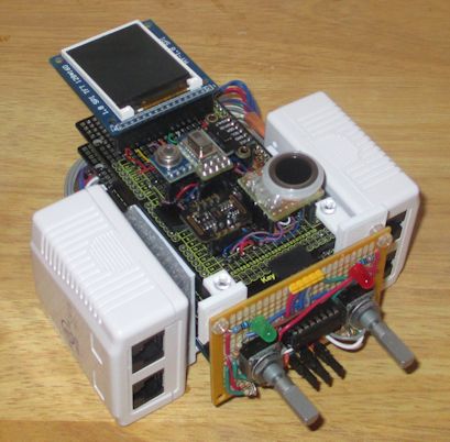
ATTiny85 Token Box
|
- ATTiny85 Token
- Reset Switch
- PCB
Box/Case
|
|
Units
Breakdowns
ATTiny85 Token
Connections
Code (Updated 11/16/2021)
Special Libraries
#include <Adafruit_GFX.h>
#include <Adafruit_ST7735.h>
#include <Adafruit_VL53L0X.h>
#include <Adafruit_AMG88xx.h>
#include <MAX30105.h>
#include <SparkFunMLX90614.h>
#include <DFRobot_ID809.h>
#include "bmpHeader.h"
#include <SD.h>
#include <Adafruit_MPU6050.h>
#include <Adafruit_Sensor.h>
#include <pu2clr_pcf8574.h>
Library Modification
// In this Library : #include <SparkFunMLX90614.h>
//Change the following line in the bool IRTherm::I2CReadWord(byte reg, int16_t * dest) routine.
//
//  I2C processing change needed for Arduino Due implementation
//
// Comment Out Line Below
//	_i2cPort->requestFrom(_deviceAddress, (uint8_t) 3, (uint8_t) true);

// Add Line Below
      _i2cPort->requestFrom(_deviceAddress, (uint8_t) 3, (uint32_t)reg, (uint8_t)1, (uint8_t)true);
Code Listing
Pseudo-Medical Monitor Code
Main Pseudo-Medical Monitor Page
Pseudo-Medical Monitor


