Pseudo-Medical Monitor
What is this device?
This device is the ultimate Pseudo-Medical device not having any form of endorsement whatsoever! This is NOT A VALID MEDICAL DEVICE IN ANY KNOWN UNIVERSE, ACTUAL OR FICTIONAL!!!
Why make, let alone market this device?
This product was part of the underground QUACK-A-THON 2025 contest. It was built as an alternate universe Hack-A-Day prize entry intended to bring mankind to its knees. After defeating several other malpractice devices, immediate marketing was authorized with little regard to the reality of the project.
How does it Pseudo do what it does?
This device consists of a master data collection and processing unit along with external units for specialized tasking. Each External Device resides on a separate I2C bus provide through a TCA9548A I2C MUX. The external units also have a specialized embedded ATTiny85 I2C Identification Token which allows the main device to auto-configure to its attached units.
Main Device
| Device | ||||
|---|---|---|---|---|
| Device | Name | Notes | Layer Diagram | Design and Build |
 |
Pseudo-Medical Monitor |
|
 |
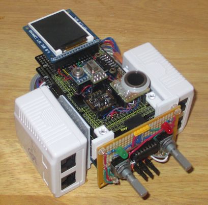
Pseudo-Medical Monitor Device Design |
Main Device Monitoring Capabilities
Extended Options
External Units
| Device | Interactions | Port Description | Connection Diagram | Design and Build | |||||||||||||||||||||||||||||||
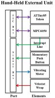
 Hand-Held Grip and Reflex Sensor |
|
|
 |
||||||||||||||||||||||||||||||||
 EKG-Respiration Unit |
|
|
 |
||||||||||||||||||||||||||||||||
 Poly-Liar Unit |
|
|
 |
||||||||||||||||||||||||||||||||
|
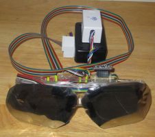
Tracking Goggles Unit |
|
|
|
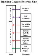
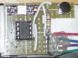
Pseudo-Medical Monitor Tracking Goggles External Unit Design | |||||||||||||||||||||||||||||||
|
Hypno Goggles Unit |
|
 | |||||||||||||||||||||||||||||||||
 EEG Unit |
|
|
 |
||||||||||||||||||||||||||||||||
Test Capabilities with and without External Units
| Test | |
|---|---|
| Configuration | Procedure |
| Eye Test | |
|
Instructions for the one being tested are displayed on the unit's screen. The one tested will be shown an "E" symbol of various sizes and orientations. The display will be activated based on distance readings from the Base Device distance sensor. After the display distance and time are met, the one tested will use a Rotary Encoder and Switch function, on the Control Panel, to select orientation on the "E" symbol. The process will be repeated with success or failure counts by orientation and distance will be recorded. |
| Hearing Test | |
|
Instructions for the one being tested are displayed on the unit's screen. A series of tones of various frequencies and volumes are played to each ear in variable patterns. Upon detection of the Tone, the tested is required to signal detection by depressing the appropriate Hand Held Unit Button of Rotary Encoder. Tones are tested for a determined time and a timeout condition is considered to be non-detection. Repeat of the "missed" Tones can be retested for confirmation. |
| Grip and Reflex Test | |
|
Instructions for the one being tested are displayed on the unit's screen. The one tested will be asked to grip the Hand Held Units multiple times to set a baseline for grip pressure readings for each Unit used. The one tested will then be required to register detection of the Units vibrating motor. The operating time of the motor will be varied. Detection of the vibration and time to detection are recorded. Detection will be based on grip detection and Unit Button depression as instructed during test. |
| EKG and Respiration Test A | |
|
Instructions for the one being tested are displayed on the unit's screen. The victim/one tested will be appropriately "Wired Up" to the device. The sensor readings will be displayed to screen. If the one tested has a pulse and breathing is detected, the the one tested will be considered "NOT DEAD". If (a pulse but not breathing) or (breathing but no pulse) is detected the the one tested will be considered "NOT QUITE DEAD". If neither pulse or breathing is detected then the one tested could simply be "PINING FOR THE FJORDS" or "NOT ALIVE" but no assertion will be made as to their death. |
| EKG and Respiration Test B | |
|
Instructions for the one being tested are displayed on the unit's screen. The victim/one tested will be appropriately "Wired Up" to the device. The sensor readings will be displayed to screen. Regardless of the sensor readings, the NeoPixel Unit on the EKG Unit will be cycled through various colors, brightness and/or sequences. Changes to sensor readings will then be wrecklessly assigned to conjecture as well as confession through projection interpretations. |
| EEG Test | |
|
Instructions for the one being tested are displayed on the unit's screen. The victim/one tested will be appropriately "Wired Up" to the device. The sensor readings will be displayed to screen. Regardless of the sensor readings, the NeoPixel Unit on the EEG Unit will be cycled through various colors, brightness and/or sequences. Changes to sensor readings will then be wrecklessly assigned to conjecture as well as confession through projection interpretations. This is a test of higher validity due to there being more lines displayed on the screen then the EKG and Respiration Tests. |
| Poly-Liar Test | |
|
Instructions for the one being tested are displayed on the unit's screen. The victim/one tested will be appropriately "Wired Up" to the device. The sensor readings will be displayed to screen. After a series of harmless questions are asked and answered, the one tested will be subjected to scandalous and salacious questions and accusations. Every sensor change or stable reading will be left to predefined biased impressions and be held against the tested one's integrity. A Tone device may sound at random causing reading changes. These changes can be ignored or used as grounds to doubt the veracity of answers given. |
| Eye Tracking Analyzer Test A | |
|
Instructions for the one being tested are displayed on the unit's screen. The one being tested is warned, discouraged and berated to NOT take this test. Eye Safety has NOT BEEN ESTABLISHED. |
| Eye Tracking Analyzer Test B | |
|
Instructions for the one being tested are displayed on the unit's screen. The one being tested is asked to track a moving object with their eyes only. Movement of the head is tracked via the goggle's MPU. The ability of the tested one to hold head still is rated. Eye Safety has NOT BEEN ESTABLISHED. |
| Hypno Goggles | |
|
Just because you have this option doesn't mean you should use it and risk seizures. NOT SAFE. Don't Do This! |
What is behind the curtain?
Development and Test Units
ATTiny85 Tokens
| TOKENS | |||
|---|---|---|---|
| Device | Name | Notes | Design and Build |
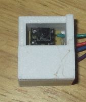 |
ATTiny85 ID Token |
|
Pseudo-Medical Monitor ATTiny85 Token |
 |
ATTiny85 Tone Token |
| |
|
|
ATTiny85 Neopixel Token |
| |
3D Printed Items
Pseudo Medical Monitor Device 3D Print
Video
Pseudo-Medical Monitor for Christmas Cheap Gift
In preparation for the expected Christmas Gift availability crisis, I present the Pseudo-Gift of the season. The time honored tradition of knockoff products hitting the market before Christmas is alive and well. What better than a multi-property knockoff device? Star Trek / Arduino / Medical knockoff device gift for everyone. This Pseudo-Medical Tricorder ripoff is the stocking stuffer for 2021.


