8th Inning
Introduction
Spin a motor, transistors and diodes
Motor - Included in your kit is a small DC electric motor. Electric motors are characterized by many different parameters such as:
- Voltage
- Current
- Torque
- Speed (rpm)
- Physical Size and shaft size
The one included can be run with as little as 1.5 volts (although very slowly) from a single cell battery up to 9 volts.
Motors tend to draw a lot of current when they start spinning. Once they are spinning this drop drastically unless they are placed under heavy load.
The maximum amount of current a small motor draws can be checked by hooking up a DC ammeter in series with the motor and physically stalling the motor shaft. Vise grips work well for this. Once you have the shaft secure, apply power and read the meter. This should be done quickly so as not to burn out the motor. Most motors can endure being stalled for a short time.
The start-up current is much more difficult to determine. I requires a meter that will record peek values or a storage oscilloscope. If your circuit can handle the maximum stalled current, then it will be able to handle the start-up current.
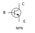
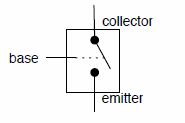
Transistor - Included in your kit a 2n2222 NPN (switching) transistor. A transistor can be thought as a voltage controlled switch. When voltage is applied to the base of a transistor, the transistor allows current to flow between the collector and emitter. This is a gross over-simplification of a transistor but it is good enough to this project.
The 2N2222 transistor included is capable of handling a current load of 600mA continuous load. This is good enough to sustain the motor spinning, but is not really recommended for this application since the start-up current for this motor is around 1.3A. The motor armature is of sufficiently low enough mass that it spins up rather quickly and therefore only draws 1.3 amps for a very short period of time. Care should be taken not to stall the motor, especially at the higher speeds, so as not to burn out the transistor.
If you want to build a more robust circuit for driving a small DC motor, you might want to consider either a TIP120 darlington transistor or a 2N3055.
For our purposes we are going to look at the transistor as just a switch that gets turned on and off by the electricity supplied by an output from the Arduino. This switch can work extremely fast compared to a mechanical one.
The transistor has 3 pins. Ours in an NPN type, which means that the the voltage on the emitter must be less than the collector, and when the voltage applied to the base (which turns the switch on) must also be greater than the emitter to turn the switch on. In order to do this we will connect our emitter to ground.
Diode allows current to flow in only one direction. Just like the LEDs from the previous Innings. In this project it is used to prevent the motor from sending power back into the circuit.
Components Needed
- Freeduino or Arduino or clone
- USB cable for Freeduino
- Freeduino development software - download here!
- Solderless Breadboard
- Hookup wire 22gauge solid
How to
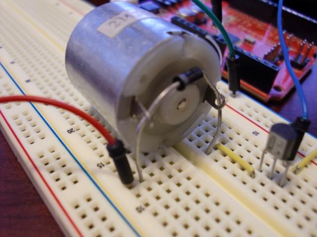
Quick no solder method to attach the motor to your breadboard.
Schematic
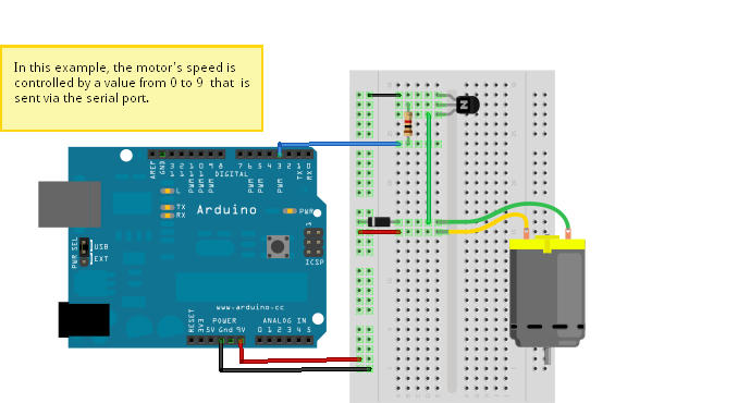
Fritzing
Code
 /*
 * Created 18 October 2006
 * copyleft 2006 Tod E. Kurt <tod@todbot.com>
 * http://todbot.com/
 *
 * based on "serial_read_advanced" example
 */

int motorPin = 3;
int val = 0;       // variable to store the data from the serial port

void setup() {
  pinMode(motorPin,OUTPUT);    // declare the motor's pin as output
  Serial.begin(19200);        // connect to the serial port
  Serial.println("Welcome to SerialMotorSpeed!");
  Serial.println("Enter speed number 0-9:");
}

void loop () {
  val = Serial.read();      // read the serial port
  if (val >= '0' && val <= '9' ) {
    val = val - '0';       // convert from character to number
    val = 28 * val;        // convert from 0-9 to 0-255 (almost)
    Serial.print("Setting speed to ");
    Serial.println(val);
    analogWrite(motorPin,val);

    Serial.println("Enter speed number 0-9:");
  }
}
Troubleshooting
- You have to change your baud rate on the serial monitor to 19200
- Make sure your power is good
- I had to uninstall and scan for hardware changes on my usb
- polarity of transistor and diode OK?
References
Here is a good explanation video of how to use transistors in a microprocessor circuit http://benkrasnow.blogspot.com/2011/05/how-to-design-transistor-circuit-that.html


