Shapeoko Repair Madness 2016
Survey the Field of Carnage
Death of the Shapeoko is just the beginning.
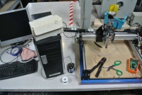
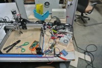
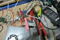
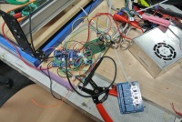
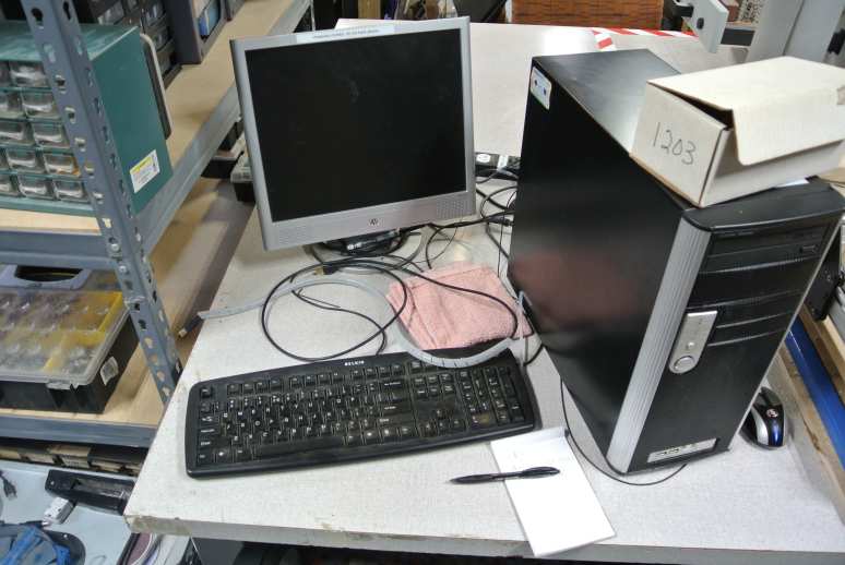
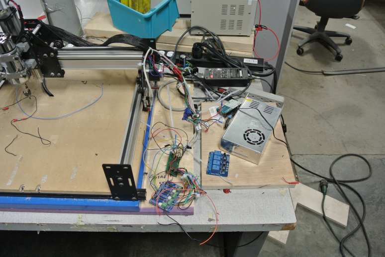
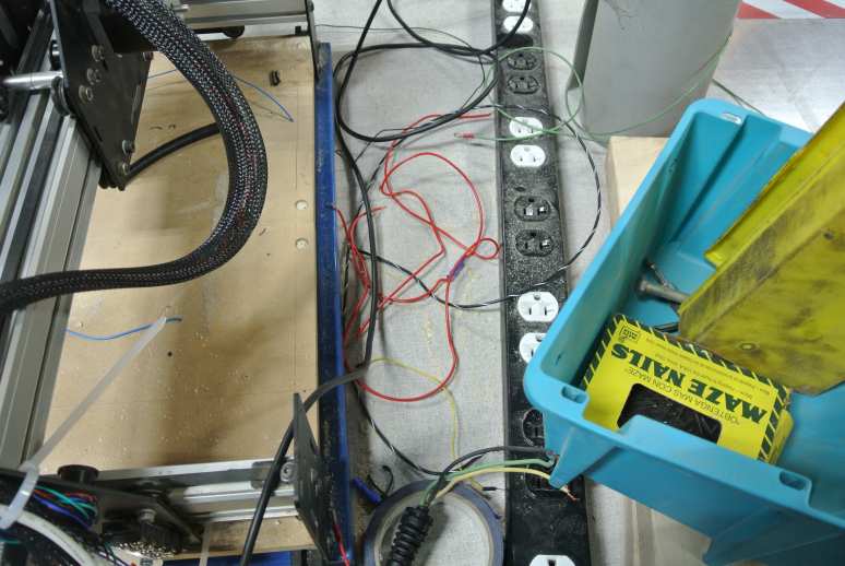
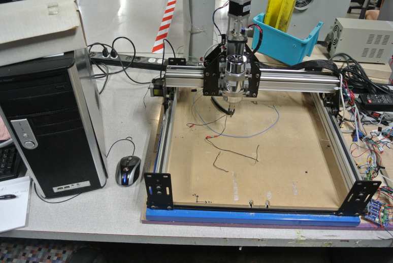
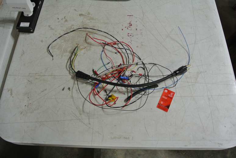
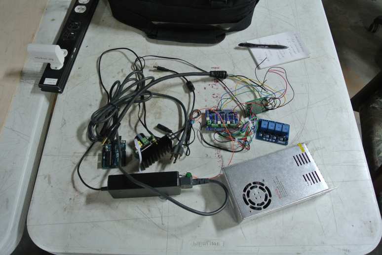
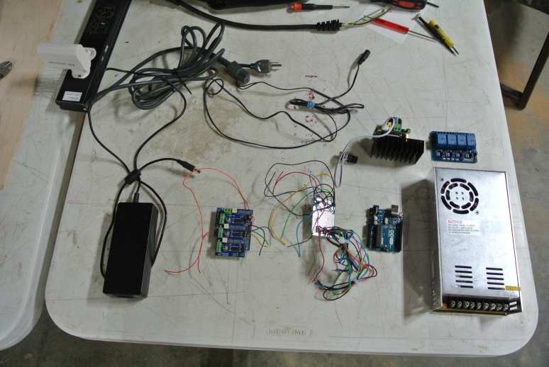
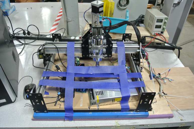
An important aspect of diagnosis is examination of the patient and the environment. In this case, a table was set aside in the hackerspace for the shapeoko. This table was meant for the "working" shapeoko and had little, if any room, for diagnostics and repair. When the shapeoko stop working, the table became the diagnostic and repair area. The following pictures show the state of the table after several attempts to diagnose and repair.
The tables was now unusable from a diagnostic and repair point of view. The solution is to clean up the area and select a suitable place to work. Rather than simply clearing off the table, I decided to remove items from the table until only the components of the shapeoko remained.
Tool Extraction
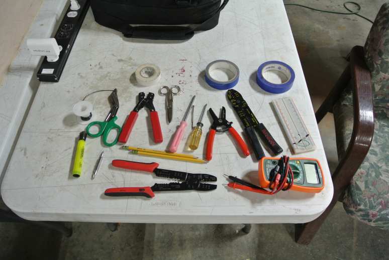
The tools below were all removed from the table. An important finding is that multiples of the same tool were found. This may indicate that multiples were needed at the same time but the tools in question and work to be performed do not support this. Instead, the multiple tools indicate multiple attempts to repair that were abandon, a single repair attempt were tools were recklessly left about or multiple repair actions in parallel. Regardless the reason, the abandoning of the tools on the table are signs of an incomplete and disorganized repair attempt. Hackerspaces can be chaotic, but a little organization when repairing equipment is of immeasurable value.
But What About Debris
The Debris Found
Debris of Value
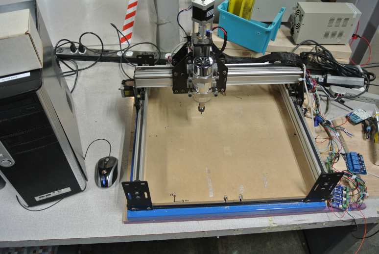
What Remains is the Shapeoko
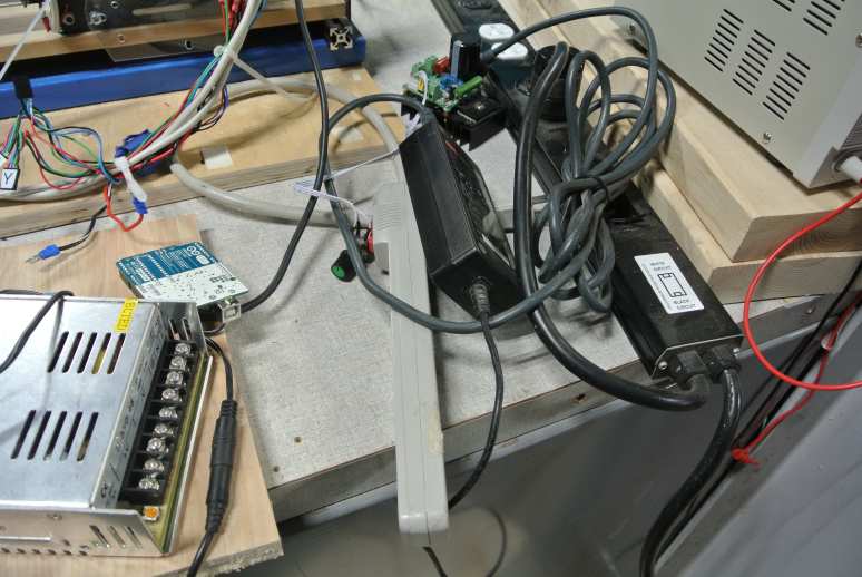
The Electronic Guts and Entrails
Sorted Out Components
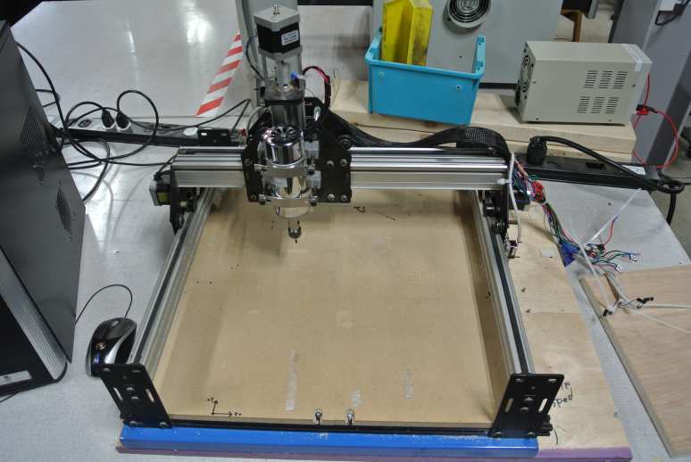
The Mechanical Beast
Post Work Cleanup and Marking
Preliminary List of Needs
Hardware
- Cables need to be labeled
- Cables need to be consistent gage and type
- Connectors need to be keyed (so they only fit together one way) and standardized
- Cable routing and securing needs to be redone
- If wire ties are used, they need to be trimmed
- Limit switches need to be securely mounted and wired
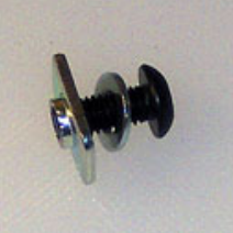
- Mounting hardware for table is missing an insertion nut
- Attach spindle to keyed connector
- Control boards need to be tested
- Stepper motors need to be tested
- Determine heat sink and cooling fan needs for control boards
- Determine whether control board interfaces with spindle
- Research alternatives for controllers and connectors
- Research alternatives for table materials & mounting
- Mount all power and control in a box with keyed cable connectors
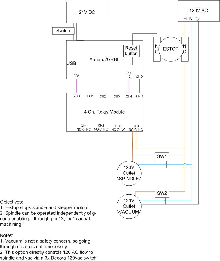
- Install emergency stop button
photo of missing insertion nut
The insertion nut is the rectangular piece. M5 thread, 10mm x 15mm x 1.5mm
Stepper motor specs
Note: Stepper motors are Smart Automation SM42HT47-1684B. Specs are on this page.
Rated voltage = 2.8 V
Rated current = 1.68 A
Rated resistance = 1.65 Ohms
Rated inductance = 2.8 mH
possible e-stop solution
Note: Here's a block diagram for adding an emergency stop that looks like it may be a reasonable solution:
Software
Note: This section will be expanded when hardware issues are fixed.
- Determine whether min/max limits are stored
- Determine optimum software versions and document all settings
