Alpha Spark Detector
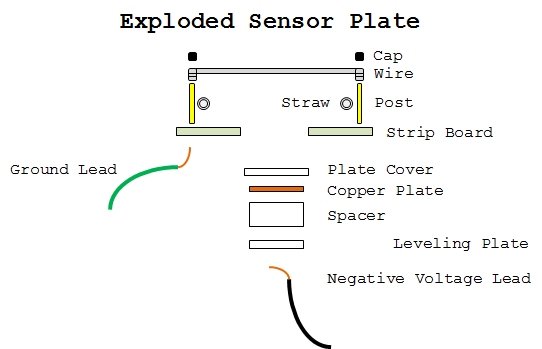
The Sensor Plate illustrated above is assembled in layers. The top layer consists of header pin spacers which are used to hold the sensor wires inplace. The sensor wires are wirewrapped to rows of header pin posts. Below the wires are straws which will tension the wire when assembled. This wire assembly is soldered onto a strip board with a square cut out of the center to allow the bottom elements to be adjusted in height and leveling. The bottom assembly begins with a Cover Plate designed to shield the Copper Plate's corner which collect charge and interfer with the operation. The Copper Plate is mounted on a space with a through hole to allow the Negative Voltage Wire to be attached. The Leveling Plate also has an access hole for the Negative Voltage Wire and serves as the mounting for the bottom assembly. Not visible in the diagram are the four leveling screws through the Strip Board and fastened to the Leveling Plate with springs between.
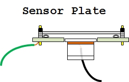
This assembled diagram shows the straws, flattened by the wires, providing tension.

