Zenbot 1216 CNC
[Equipment|Back to list of Equipment]]

|
Contents
General
|
Current status
- 29 August 2017
-
- Edited the tool table and added several of the sizes of bits that we have on hand.
- Tried using the built-in image to G-code feature. Will write up better documentation after I gather more data. Had no success with .jpg image. The code generated didn't produce any errors, but wouldn't run all the way through. Since the sample was .png format I tried that (used GIMP to convert the file) and it worked.
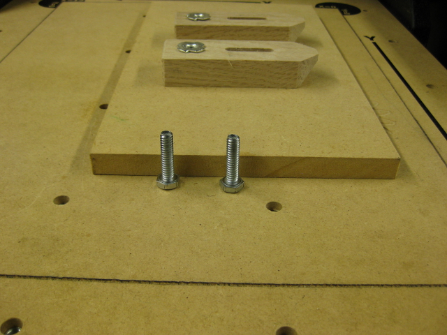
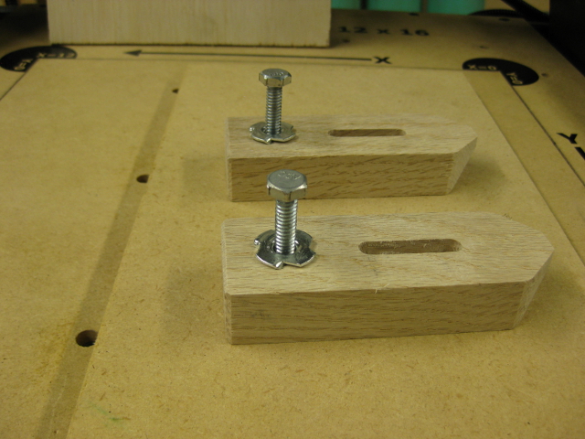
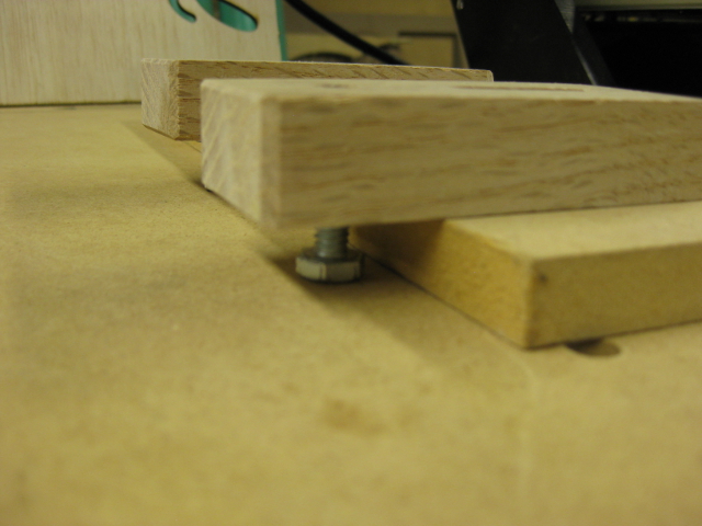
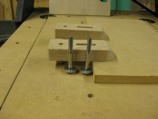
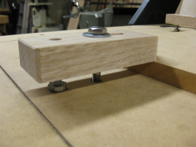
- I have made a few prototypes of the new adjustable clamps. Need to work out a couple details on the dimensions and will make better ones. Meanwhile, the prototypes do work.
- Jared has generously volunteered to assist in adding speed control to the spindle. Currently the spindle is either on or off. We plan to add both manual and software controlled speed adjustment.
- 10 August 2017
-
- Had a setback on the platform that required some rework.
- Designed and built super-sized fidget spinner that we took to Maker Faire.
- Updated operating instructions (posted below).
- 15 July 2017
-
- Worked on facing a platform that will be level with respect to the spindle. Should be ready to test this week.
- Working on another project that I plan to announce in time for Maker Faire.
- Began writing operating instructions (posted below).
- Now working under the auspices of a Makership. Thanks!
- 29 June 2017
- Recently completed
- Set up lvl1 user login
- Configured LinuxCNC under new login
- Loaded Qjoypad software
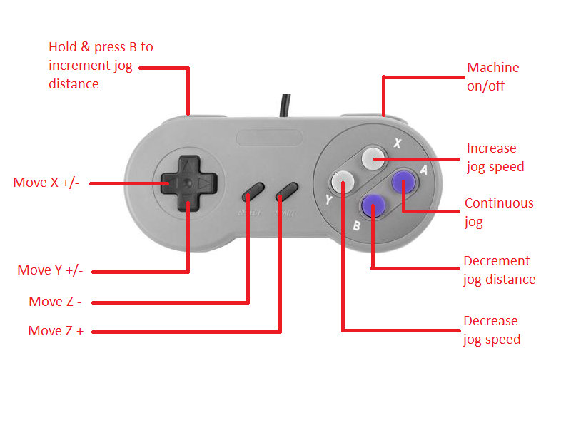
- Created layout in Qjoypad to use gamepad as pendant when aligning machine to workpiece. (See Photos section below for layout.)
- Made and tested jig for PCB milling. Need to make a better one -- maybe add leveling capability?
- Next steps planned
- Continue setup for PCB milling
- Still need to set up vacuum
- Begin writing and posting user instructions
- 31 May 2017
- Recently completed
- The Zenbot has been secured to the table.
- The E-stop button functions and has been mounted on the table.
- A power strip has been mounted to the table.
- The LinuxCNC software has been configured under the lvl1 login.
- Created a sample file using Inkscape and its Gcodetools plugin. It worked! However there was significant slipping when milling in MDF. This tool is only recommended for very soft materials.
- Next steps planned
- Configure a gamepad to work as a pendant.
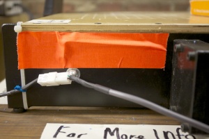
- Additional cable management, especially on wires to the limit switches.
- Test making PCBs.
- Test with other materials -- machinable wax, foam, engravable name tag/name plate.
- Load additional software.
- Make additional clamps.
- Attach vacuum to control dust.
- 14 May 2017
- We think the Zenbot is essentially in working order, but will run a few more tests.
- Here are some recent developments
- Updated the .ini file for the full 12x16 limits.
- Made and installed a new work table that shows the actual working limits of the spindle.
- The E-stop button has been wired in, but is not yet mounted.
- Here are the planned next steps
- Mount the Zenbot to the table.
- Mount the E-stop button to the table.
- Set up the Zenbot to run under the lvl1 account.
- Install additional software.
- Write and post updated operating instructions.
- Mar 2nd, 2017
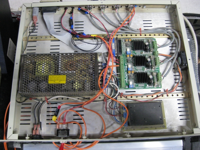
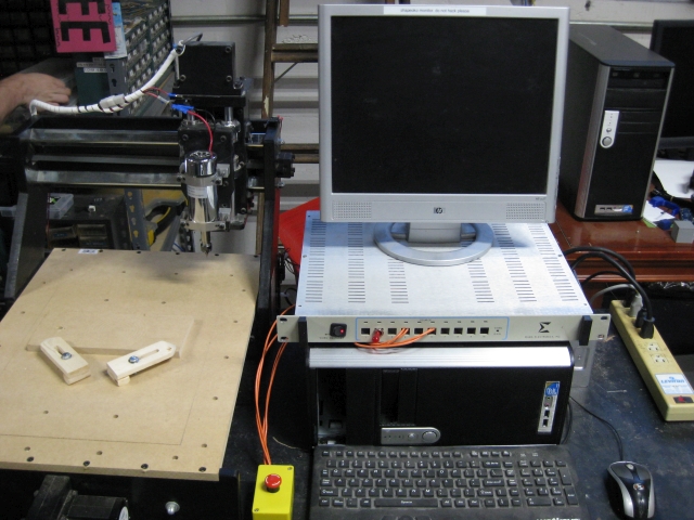
- The Zenbot 1216 (Codename:TrollMill) is now under construction and refurbishment. It is operational, has a better spindle that can mill plywood, is now at home on a mobile cart (Codename:Crashcart), has a standalone workstation with a dedicated distribution of Linux installed (Linux CNC), monitor, keyboard, Stepper controller box (Codename:RockBox), and powerstrip. We still require a big ass obnoxious E-stop and a switch for the spindle control relay (rather than just plugging it in) and a final test to release into the wilds of the LVL1 community. The TrollMill is located between the reflow oven table and the electronics components shelf in the space.
Photos (more to come)
Operating Instructions October 2017
Note: These are fairly complete, but still being revised. You are welcome to use the Zenbot at your own risk, but please document any problems you have and especially any changes you make to the set up.
LinuxCNC Doumentation:
You can access the software documentation on the computer that controls the Zenbot under the Applications Menu → CNC → LinuxCNC Documentation or from any online computer from http://linuxcnc.org/docs/2.7/html/.
Before you start:
- If you are machining wood or any other dust-producing material please roll the cart into the wood shop.
- There are NO built-in safety limits on this machine. You are responsible for making sure the tool has a clear path and does not cut into the table.
- There are several references in these instructions to a “sacrificial” board. This is simply another piece of material (usually plywood or MDF or Masonite) that you place on the table under your workpiece so you can cut through your workpiece without damaging the table.
- The resolution of this machine is about 0.001 inches (about 0.025 mm) at best. It's likely to be a little less than that.
- In testing, the belts have occasionally slipped causing to tool to follow an inaccurate path. Never let the machine run unattended. If you catch an error early, you might be able restart your program at a point before the error occurred.
- Know the location and operation of these switches:
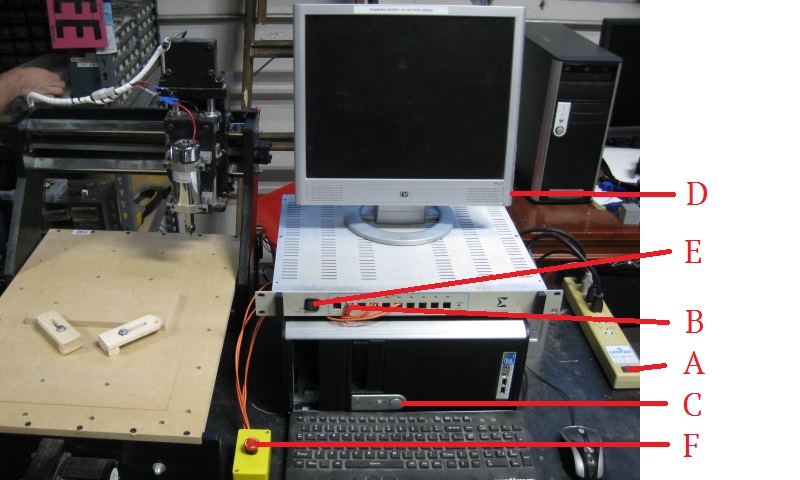
- The power strip (A) is located on the right side of the table. All equipment for the Zenbot, steppers, spindle, computer, monitor, and the vacuum are plugged in to the power strip. Make sure the spindle power switch (B) is OFF (pushed left) before turning on the power strip.
- The power switch for the computer (C) is the round button located on the front of the tower case.
- The power switch for the monitor (D) is the round button located on the right side of the monitor at the bottom.
- The machine power (stepper motors and controller) (E) is the black toggle switch with a red LED located on the front of the box on top of the computer.
- The power button for the spindle (B) is the black paddle switch located on the front of the box on top of the computer. (Next to the machine power switch.)
- IMPORTANT: Make sure this switch is in the OFF position (pushed left) except when you are running your G-code. Always wear eye protection when the spindle is turned on.
- We currently have no speed control on the spindle. It is either off or on.
- The E-stop button (F) is the red button on the yellow box mounted on the table next to the Zenbot. Pressing the E-stop button disconnects both the machine power and the spindle power. Reset the E-stop button by turning it to the right (clockwise) about 30 degrees.
Powering Up:
- Make sure the switch for the spindle power is in the OFF position. The spindle power switch is the red toggle switch on the front of the power/controller box.
- If you will be using the pendant (gamepad) make sure it is plugged in to a USB port.
- Turn on the power strip on the right side of the table.
- Press the power button on the front of the PC and turn on the monitor.
- After the computer boots up log in as lvl1 with the password whatpassword.
- The software for the pendant (gamepad), Qjoypad, and the software for the Zenbot, LinuxCNC, are both set to autostart when you log in.
- The layout for Qjoypad is called Set_User_Coords and should load on startup unless someone creates a new layout. (The most recently used layout always loads by default, so if you create and use a new layout it would be excellent of you to change it back before logging out.) Right-click on icon that looks like a game controller on the taskbar to see which layout is loaded.
- The interface for the Zenbot CNC Mill is called AXIS.
- Make sure the machine power is ON and the spindle power is OFF. Machine power must also be turned on in the software. You can do this by:
- Pressing the F2 key on the keyboard
- Choosing Machine → Toggle Machine Power from the menu
- Clicking on the square orange button on the toolbar under the main menu
- If you are using the pendant, by pressing the button labeled R (see picture below)
- Select the Manual Control tab (or press the F3 key).
- Before homing the Zenbot make sure there are no obstructions in the path of any axis. Also, the homing process will fail if any limit switch is already pressed before homing starts. When you finish working on the Zenbot please “park” the axes 1 inch from the limit switches. (See Shutting Down procedures below.) If the previous user failed to do this, use either the Manual Controls or the pendant controls to move the axes before homing.
- Home the axes. You can do this by:
- Pressing CTRL-Home on the keyboard
- Choosing Machine → Homing → Home All Axes from the menu
- Clicking the Home All button
- Wait while the Zenbot homes. The axes home in the order Z (up), X (right), and Y (back).
- If you home the Zenbot and the X,Y,Z coordinates under the Preview or DRO tab are NOT all zero, then either the software closed unexpectedly or the previous user failed to clear all offsets before shutting down. As this can adversely affect your work, you can follow the instructions for clearing offsets under the Shutting Down section below before continuing. Then home the Zenbot again.
- Make sure the machine power is ON and the spindle power is OFF. Machine power must also be turned on in the software. You can do this by:
Changing Bits
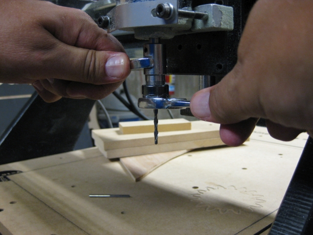
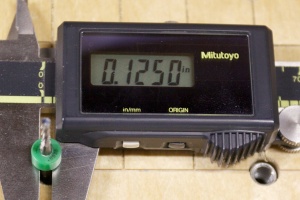
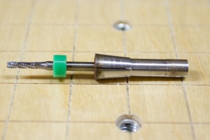
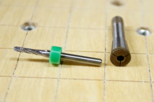
- The standard collet (the part of the spindle that actually holds the bit) takes tools with a 1/8 inch diameter shaft. There are several bits in the storage bin beside the computer. Please make sure you choose the correct tool (s) for your project, that you mount them correctly, and that you store them properly.
- This is the same diameter as many Dremel tools which may work for some projects, but any tool you use is at your own risk. Many factors affect the quality of your output including the bit, the spindle speed, the feed speed, the depth of cut, and the material you're cutting.
- If you need to change the bit for your project you will need two open-end wrenches -- 1/2 inch and 11/16 inch.
- Move the spindle to a position where you can reach it easily.
- Press the big red E-stop button next to the Zenbot. This will prevent any accidental movement of the steppers or spindle which could cause damage or injury.
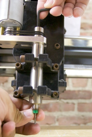
- There are two flat spots on the sides of the spindle shaft above the collet. Put the 1/2 inch wrench on those flats with your left hand.
- Put the 11/16 wrench on the collet with your right hand.
- Gently pull both hands toward yourself and the collet will loosen.
- The standard collet (the part of the spindle that actually holds the bit) takes tools with a 1/8 inch diameter shaft. There are several bits in the storage bin beside the computer. Please make sure you choose the correct tool (s) for your project, that you mount them correctly, and that you store them properly.
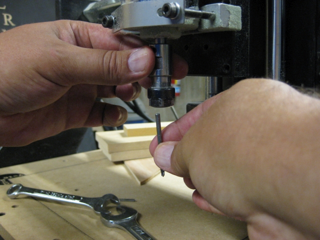
- The bits have sharp edges so handle them with care. Remove the old bit and then insert the new bit. Turn the collet with your fingers to hold it in place.
- The bits have sharp edges so handle them with care. Remove the old bit and then insert the new bit. Turn the collet with your fingers to hold it in place.
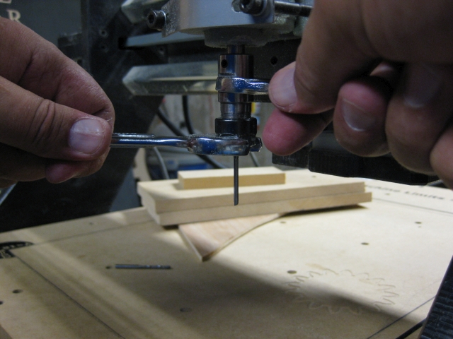
- Put the 1/2 inch wrench on the flats of the spindle this time with your right hand.
- Put the 11/16 wrench on the collet with your left hand.
- Gently pull both hands toward yourself and the collet will tighten.
- Store the unused bits properly. Hard surfaces (such as other bits, for example) can damage and dull the cutting edges.
- Give the E-stop button a partial turn to the right to restore power. (You typically also have to press the F2 power button after an E-stop.)
- The "workhorse" of the milling bits is the ball nose end mill. If you use a different bit for your project, please be kind and put one of these back in the spindle before you leave.
Loading and Running a Program
- Never leave the Zenbot running unattended. Seriously. Never. Not for any reason or any length of time.
- The programs for CNC machines are basically text files containing a series of instructions called G-code.
- Simple G-code programs can be created by hand with a text editor, but typically they are generated with CAM (Computer-Aided Manufacturing) software such as the G-code Tools extension in Inkscape or more sophisticated programs like VCarve (which also includes design and editing tools).
- If your G-code includes any coordinate that is outside the limits of the Zenbot the program will not run.
- The limits of the Zenbot are X = 12 inches (304mm), Y = 16 inches (406mm), and Z = approximately -3.5inches (-89mm). The Z limit depends on the length of the tool being used and any supporting/sacrificial materials under your workpiece.
- These are absolute values from the Machine Coordinates origin (home) position. For example, if your Work Coordinates are offset to the center of the table then your work limits are from -6 to +6 on the X axis and -8 to +8 on the Y axis. The Z axis may likewise include positive and negative values because the Work Coordinates origin are typically set below the upper limit of the machine.
- The limits of the Zenbot are X = 12 inches (304mm), Y = 16 inches (406mm), and Z = approximately -3.5inches (-89mm). The Z limit depends on the length of the tool being used and any supporting/sacrificial materials under your workpiece.
- Bring your program to the computer on a thumb drive. You may temporarily copy it to the desktop for convenience, but if you do please delete it when you are done.
- The default file extension for programs in LinuxCNC is .ngc, however as long as the file itself is properly formatted that shouldn't matter. (Some on-line simulators require a .gcode file extension and those run just fine.)
- To open a program you can
- Use File → Open from the menu OR
- Press the letter O on the keyboard
- Navigate to where your program is stored
- LinuxCNC scans the code as it loads and may give an error message if required elements are not included or if unknown elements are included. You must fix these errors and reload the program before running it.
- Turn the spindle on before running the G-code. Always wear eye protection when the spindle is turned on.
- To run a program you can
- Use Machine → Run program from the menu OR
- Press the letter R on the keyboard OR
- Click the blue triangle (not the arrow) on the taskbar.
- Never leave the Zenbot running unattended. Seriously. Never. Not for any reason or any length of time. (It's worth repeating.)
- While your program runs, be prepared to stop it at any time. Sometimes workpieces slip out of position or a belt/stepper motor gets bogged down or there is a glitch in the software.
- You can stop a program by
- Pressing the big red E-stop button which will stop all the axes and the spindle OR
- Pressing the Esc key on the keyboard which stops the axes but NOT the spindle OR
- Use any of several methods to turn off machine power which stops the axes but NOT the spindle
Running a Program for the First Time
- While your program runs, be prepared to stop it at any time. Sometimes workpieces slip out of position or a belt/stepper motor gets bogged down or there is a glitch in the software. (It's worth repeating too.)
- If you are running a program for the first time you should consider trying it without the workpiece on the table to check for clearances.
- If you are cutting through the workpiece please place a sacrificial board under it to protect the table. This could be a thin piece of plywood or Masonite – as log as the distance below your workpiece does not exceed the thickness of the sacrificial board.
- Determine the position of any clamps/vises you plan to use and ensure that they are not in the path of the spindle.
- Bolts that protrude more than about ¼ inch below the table will block the Y axis travel.
- If you are checking for clearances you don’t need to turn on the spindle, but if you do make sure you wear eye protection while the spindle is on.
- You might also go through the program (or certain parts of it) one line at a time.
- Use Machine → Step from the menu OR
- Press the letter T on the keyboard OR
- Click the blue arrow (not the triangle) on the taskbar
- When you are certain that there are no errors in your program and that all clearances have been checked, mount your workpiece.
Mounting Your workpiece
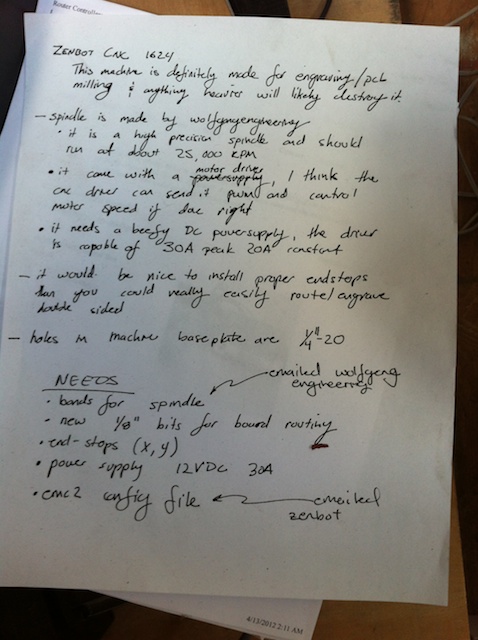
- Mount your work on the Zenbot table. The mounting holes have a standard 1/4-20 thread.
- A sacrificial board is simply another piece of material (usually plywood or MDF or Masonite) that you place on the table under your workpiece so you can cut through your workpiece without damaging the table.
- Never try to hold a workpiece by hand while machining.
- See the next section for more information on using the table clamps. There are three basic methods of securing your work:
- Bolt, clamp, or tape your workpiece directly to the Zenbot table. The mounting holes have a standard 1/4-20 thread.
- The “Damage-Free Hanging” tabs from 3M have worked well for small, light-weight pieces and they remove cleanly. If you use regular double-sided tape, please use a sacrificial board over the Zenbot table.
- Bolt, clamp, or tape your workpiece to another board (a sacrificial board, for example, but it could also just be a way to secure an odd-shaped piece) that you can bolt or clamp to the Zenbot table.
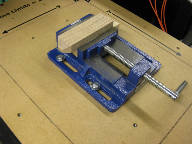
- Bolt a vise to the Zenbot table and use the vise to hold your workpiece. Be especially careful that the spindle stays clear of the vise at all times.
- Bolt, clamp, or tape your workpiece directly to the Zenbot table. The mounting holes have a standard 1/4-20 thread.
- Make sure all clamps/bolts/vises are not in the path that the spindle will follow. The spindle may go above a clamp/bolt/vise if you have sufficient clearance in your G-code.
- Likewise, make sure that as the spindle moves across your workpiece you have sufficient clearance in your G-code to avoid unintended contact.
- Make sure that all bolts and clamps are appropriately sized for your work piece. Bolts that protrude more than about ¼ inch below the table will block the Y axis travel.
- The Machine Coordinates origin (0,0) point of the Zenbot is in the back right corner. Positive X is to the left and positive Y is forward. This means it will cut upside down and backwards to the way you normally view your work. Position your work accordingly.
- Mount your work on the Zenbot table. The mounting holes have a standard 1/4-20 thread.
Using the Table Clamps
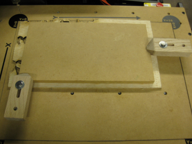
- The table clamps are adjustable to fit a variety of workpiece thicknesses. They are versatile, but depending on the size and shape of your workpiece may not be the best choice. In those cases secure your workpiece to another board that can be clamped or use a vise bolted to the table.
- Always use at least two table clamps.
- Choose bolts that are slightly longer than the thickness of your workpiece (plus sacrificial board if you're using one). These go into the T-nuts on the bottom of the clamps and need to be adjusted so that the clamp is parallel to the table. It's okay if these project above the top of the clamp as log as they remain below the safe Z height.
- Choose bolts that are slightly longer than the thickness of your workpiece plus the clamp (plus sacrificial board if you're using one). These go through the top of the clamp (use a flat washer) into T-nuts that are embedded in the table.
- If these bolts project more than about ¼ inch below the table they will interfere with the movement of the Y axis.
- Choose bolts that are slightly longer than the thickness of your workpiece plus the clamp (plus sacrificial board if you're using one). These go through the top of the clamp (use a flat washer) into T-nuts that are embedded in the table.
- Make sure the clamps are positioned so that they will be clear of the spindle while running your program.
- Tighten these with a wrench just enough to hold the workpiece securely. Over-tightening can damage the table, the clamps, or your workpiece.
Aligning to Your Workpiece
- Your work will rarely line up with the Machine Coordinate home position of the Zenbot. CNC machines use Work Coordinates while cutting that are offset from the Machine Coordinates of the homing process.
- You need to know where the origin for all three axes (0,0,0) are for the design of your work piece. It may or may not be located at a corner or the center of your raw material.
- Move the steppers so that the spindle lines up with each Work Coordinate 0. The pendant is useful for aligning the spindle with your work because you are more free to move where you can see than when using the keyboard or mouse.
- Select the X, Y, or Z radio button on the Manual Control tab and click the Touch Off button on the Manual Control tab. You can be anywhere along the origin line when you set the Machine Coordinate. (That is, you don't have to be at 0,0,0 to set all three. You could have the spindle out in the middle of your work piece to set Z to zero, then anywhere along the right edge to set X to zero, and then anywhere along the back edge to set Y to zero.)
- There are actually several sets of Work Coordinate offsets. You might set one for machining your part and another for a convenient place to change tools, for example.
The Pendant (gamepad)
Shutting Down
- Some parameters (offsets in particular) are stored when LinuxCNC shuts down. This may be convenient if your are returning to machine more of the same parts with the same set-up, but may be confusing to other users. Therefore we recommend the following procedure to clear all the offsets and prepare the machine to be turned off.
- Make sure there is nothing that might obstruct the movement of the Zenbot – remove all workpieces, clamps, etc.
- To clear all offsets:
- Open the file “clear_down.ngc”
- Use File → Open from the menu OR
- Press the letter O on the keyboard
- The file is located in the directory /home/lvl1/linuxcnc/nc_files
- You might also find it under the menu File → Recent Files
- Run the program
- Use Machine → Run program from the menu OR
- Press the letter R on the keyboard OR
- Click the blue triangle (not the arrow) on the taskbar
- Use File → Quit on the menu to exit the LinuxCNC software.
- You can also quit by clicking on the Close Window button (the X in the top right corner of the window) but a dialog box will pop up asking you to confirm that you want to quit.
- Open the file “clear_down.ngc”
- Click on the Log Out Dialog button on the desktop taskbar and choose Shut Down.
- Secure all materials, clamps, vises, etc.
- Use the vacuum to clean up any dust or shavings.
- Before turning off the power strip place a block under the spindle. It tends to drop when power is removed which can damage the tool and/or the table.
- Turn off the power strip.
Legacy Info
Everything below this line on this page may be out of date, but is being preserved throughout the update process.
Operating instructions (Legacy info)
As-of-Dec-2012 the equipment can be operated with extreme caution.
- Given the lack of
- limit switches
- emergency power off
- cleaned up software
- There is a high risk that the machine will be damaged if used. If you really want to work with the machine now its STRONGLY recommended that you have Chris Pettus or Mike Lutz sit with you the first time you try and use the machine.
More instruction will be coming in the future, but the best thing you can do now is pick and learn a 3d CAD package. They are shockingly hard to use and you should expect spend 8+ hours going through the tutorials in order to drive the system such that all the faces have the surfaces you want and also learning how to use the snap systems to align things in 3d space (all of which will be critical when the file is handed over to the CAM software)
If you happen to be working on OS X, the popular commercial hobbyist-targeted 3d CAD Rhinoceros is freely available while it continues to be in development (see: http://mac.rhino3d.com). I think the primary appeal of Rhino is that it has a very good tutorial (... well, and its free for OS X ... for the moment)
Materials tested with zenbot (Legacy info)
- Machinable wax
- Cuts easily - though not cleanly. Still learning
- RenShape 460
- Cuts easily and cleanly. Only had good experiences with it so far
- Green-blue rigid foam (unsure what it is, was found in scrap box)
- Cuts cleanly and easily, but kicks up static-attracting bits of foam, likely to fowl the mill if not cleaned while cutting
- Some kind of fiber board (found as scrap)
- Sloppy cuts, details tend to break off
- Some kind of clear plexiglass (found as scrap)
- BAD: within a few minutes of cutting, the plastic formed on the blade, completely isolating the cutting surfaces
Equipment Description (Legacy info)
Parts that make up this system:
- Zenbot itself (Includes the body, armatures, and the x, y, and z motors and actuation hardware (belts))
- Believed to be a Zenbot 1216 zenbot 1216 product page Zenbot 1216 manual
- X, Y, Z motor controller
- Believed to be a Mechatronics 3-axis CNC micro-stepper motor driver mechtronics 3-axis
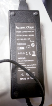
- Power brick for X, Y, Z controller
- Labeled "PA3290U-2ACA SEB 100P2-15.0". Input 100-240v 2.5A 50/60Hz. Output 19V at 6.3A. Center of connector is plus, outer shield is minus.
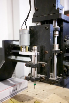
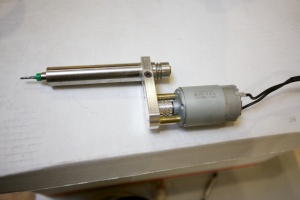
- Spindle (the routing part) - Believed to be a Wolfgang Engineering ... um ... spindle? (they don't seem to have any model info on the spindle or historical information on the website)
- Wolfgang engineering website
- The belts needed to couple the motor to the spindle were missing but have been replaced by the smaller belts from faucet repair kit.
- Gerrit has talked with Wolfgang about this and he may have enough info to order the belts as parts (They may effectively be big O-rings)
- The info Gerrit received (with regards to the o-rings) didn't match our spindle. Chris P found a match by trial and error
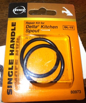
- The smaller o-rings from a DL-15 Single Handle Delta Kitchen Spout Repair Kit seem to be a "good enough" match to the belts that are needed for the spindle. As of Nov 6, 2012, these are the belts on the spindle.
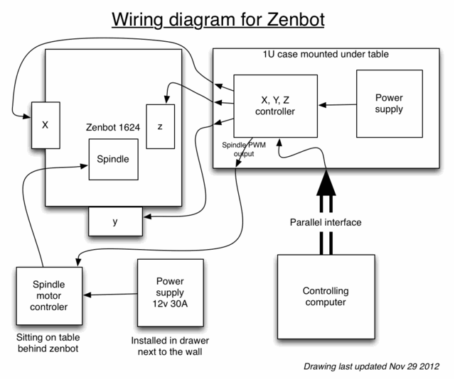
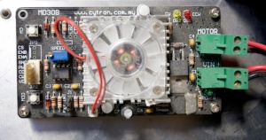
- Spindle motor controller
- Cytron Technologies MD30B
- Spindle power supply
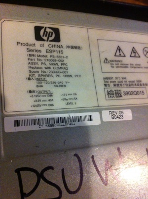
- An HP/Compact server powersupply "ESP115" from the boneyard.
- Documentation for the MD30B controller says that it wants between 10 and 30Vdc with with a peak (output) of 30A (at 12Vdc?). Current product from wolfgangengineering has 200W 12Vdc motor, so 30A peek seems possible.
- Computer running EMC2 CNC control software and that has a parallel port
- Thin dell desktop sitting with the zenbot.
- Bits
- There is one bit with the Zenbot, but to be of use more will have to be acquired. There seems to be agreement that the best way is to buy of Ebay, more digging will be needed to understand what to buy and how to re-cert/re-measure it in order to make it usable with the machine.
Pictures (Legacy info)
Notes from initial equipment build (Legacy info)
Log of research (newest to oldest) (Legacy info)
Mar 02 2017 -CaveTroll-
Much progress has been made to this relic. A new, pictures inbound soon.
Nov 12 Mike L
- Copy of update email -
Virtually all progress in this update (and most from last) is thanks to the continued heroics from Chris Pettus. He is the unsung hero of this project and will be the reason the machine gets to whatever level of operation that it gets to.
Detail for this week:
- Progress made:
- Chris P found some < $4 faucet o-rings that are the right size to link the spindle motor to the spindle arm
- They are installed on the zenbot, have about 30 min of time on them, haven't shown any issue with wear or slippage.
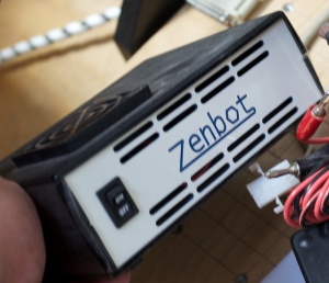
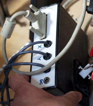
- Spindle power supply interface case built with integrated fuses
- currently fussing the spindle at 10 amps, though the power supply really should be able to drive 30 amps safely, we are using the low fuse to better learn what the spindle will really need -- In other words, if anyone tries to cut something really hard (or jams the cutter) the spindle fuse will likely blow.
- I expect we will increase the fuse as we better understand the spindle (unless we find it never blows)
- Last meeting, with the help of many other Lvl1'er, the Zenbot was moved down stairs next to the big CNC.
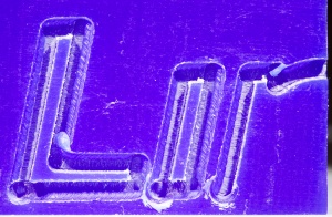
- Running the spindle at full speed (likely too fast for the wax) Chris P and Mike L did a cut of the first few letters of "LinuxCNC" in machining wax. See the wiki page for full desc or jump here for picture: http://wiki.lvl1.org/File:Zenbot_Clockwise_cut_(first_cut).jpg
- The spindle motor speed controller has been repaired and tested with a separate motor, not yet integrated back into the zenbot.
- Chris P found some < $4 faucet o-rings that are the right size to link the spindle motor to the spindle arm
- Next actions:
- Get the speed controller installed between the spindle and its supply (also, perhaps trying to connect the PWM interface to LinuxCNC) - Chris P
- Measuring spindle speed (at full and different settings of the speed controller - Chris P and Mike L
- Writing up the software complexities of working with the CNC (Need CAD & CAM before can use LinuxCNC) - Mike L
- Learning various CAD and CAM packages so-as to create g-code that we can mill with the Zenbot - Mike L, Chris P, and anyone else who is thinking they want to use this system
- Future/dream/stuff-it-would-be-nice-if-other-people-would-jump-in-and-tackle:
- More bits for the Zenbot
- We now know that the collet in the zenbot takes 1/8" bits (... and given the collet is high-spec it will likely ONLY take 1/8" bits - it might be able to take 3mm bits, but I wouldn't be surprised if they slip given the collet design
- The bits for the spindle are both expendable (very breakable and will dull if cutting hard stuf) and kinda pricy (new < 1mm blades seem to be around $35 new).
- As talked about in the last update, multiple parties have said "get used blade off ebay", and while I'm starting to understand what they are talking about, I'm still not ready to plunge into the used blade world, nor has anyone committed to this work.
- So I can keep working, I'm going to personally order a few new blades for my personal use and use the experience to better learn about the used market. For anyone else thinking about using the zenbot in the near term, I guess what I'm saying is "for the time being, the zenbot is a 'bring your own bits' device". (I'll add a bit ordering guide to the wiki as I better understand the process)
- X, Y, Z limit switches
- Chris P has some switches which may be quite good for this, we are not sure when or if we will get to this though (neither of us are mechanicals, so making readjustable and robust mounting brackets for switches is a bit baffling to us)
- X, Y homing and measuring the cutter in the Z
- X & Y homing might be doable with the limit switches depending on what the controller can do. Measuring Z will likely require something new. Chris P has this in mind when he is working with the X,Y,Z controller but no new work has been done on it since last update
- Integrated vacuum system
- Gerrit said at last meeting that he might have a vacuum that could be used for this. I have a 15A ac power relay (http://adafruit.com/products/268) that might also be able to be used, but no planning other then ideas of parts have been done.
- Sacrificial milling surface overlays and/or jigs
- Chris P, Gerrit and I have all agreed that it would be very good idea to build some type of sacrificial overlay over the Zenbot milling surface given how easy it is to drive the blade right through the mills surface (the -z limit won't help for this, the spindle is such that the cutting blade would always go through the mills surface before the limit hit)
- More bits for the Zenbot
With that said, no one has picked up the ball on this, and I doubt Chris P or I would any time soon. Help would be welcome, especially if you know what your doing with the big CNC and/or know how useful jigs would be built for specific tasks, like circuit board milling
- All-in-one enclosure
- Gerrit has been dreaming of an all-in-one enclosure for the zenbot, with its controls, and the computer system that LinuxCNC runs on packed underneath the zenbot. (something like http://buildyourcnc.com/redSproutCNCComputerSystem.aspx under the zenbot) Chris P has continued to refine/repack the control electronics and this may be relatively straightforward in the furture but no one has taken the ball for this task.
- All-in-one enclosure
The CNC is nearly at the point where different tracks of work will need to be done for different projects (molds vs. circuit boards).
I'm interested in 3d mold making and to get the ball rolling for that sub-project on the zenbot, I've started a new wiki page about that use: http://wiki.lvl1.org/Copying_Guerrilla_guide_to_cnc-mold-casting (I've also ordered a board of Renshape 460 - millable plastic for mold making - that I would be up for selling parts off of for anyone else wanting to try 3d part mold making)
I know that a number of other people in the group are interested in cutting circuit boards, thats not really my cup-of-tea (at least not until I have my brain wrapped around the mold making stuff) so I'm hoping some of the other interested parties will jump in, start researching the software/router-bit/jigs that are required to do that work, and building documentation to teach others.
-Mike
Nov 8 Mike L
The included bit has been measured and is 1/8", pressumibly this is really the only size the collet can hold (Might be able to hold a 3mm bit but the teeth on the collet were so close, a 3mm might slip)
Numerous pictures were taken of the collet system, later to be use for instruction.
Nov 6 Mike L
Through heroic effort of Chris P, all the major drive systems of the CNC are now online (Power found for spindle, drive belts found for spindle, software for X,Y,Z all calibrated)
With the help of Chris C, Nathan and a few others the Zenbot was moved downstairs next to the big CNC.
An initial cut was done in machine wax of the "LinuxCNC" default on LinuxCNC (only the "L", "i", and 1/4 of the "n" fit on the wax)
Nov 5 Mike L
Copy of status update email:
- Progress made:
- The x and y stepper control wires were switched and the Axis config rewritten for X,Y,Z such that motion is true to Zenbot docs and is also much closer to real-world measurement (Was > 730% off, now estimated at < 1% of real world) - Chris P
- Belts for the spindle are on order - delivery unclear, worst case expected before Nov 16th - Mike L
- Motor controller blown - replacement motor control IC expected yet this week - Chris P
- Next actions:
- Directly test spindle motor make sure its isn't the cause of the trouble with the controller - Mike L & Chris P
- (as parts come in)
- Install/test belts connecting the spindle motor to the spindle rotor. - Mike L
- Repair/troubleshoot spindle motor controller. - Chris P
- Run a test milling using soft material (machinable wax) - Mike L
- Run test milling to better lock-in the real-world vs. software measurement accuracy. - Chris P & Mike L
- Unaddressed needs:
- More spindle bits - have been told to "carefully" order off of ebay
- Gerrit may pick this up, but if anyone else out there wants to take charge of getting and calibrating rough and fine milling bits off of ebay let me know.
- More spindle bits - have been told to "carefully" order off of ebay
- Future/dream stuff:
- Add limit switches to X,Y,Z -- important to prolong the life of the machine
- Chris P has switches on order - still lots of planning to figure out how to install and use
- Add homing switches for X,Y,Z -- required to allow high resolution milling and/or double sided alignment for circuit board cutting
- Chris P has switches on order - still lots of planning to figure out how to install and use
- Sacrificial milling surface overlays and/or jigs - surfaces that would screw in the zenbot surface to increasing the distance the mill would have to improperly travel before it started destroying the Zenbots primary surface. Best made on-mass, likely using the big CNC in the basement. A subset should also be created for specialized use of the mill (alignment pegs for circuit board milling, etc)
- No work done, no one offering to do the work
- All-in-one enclosure -- Desire of Gerrit
- One of Gerrit's ideas - no significant planning or sourcing has been done to make this happen
- Vacuum system -- Desire of Gerrit
- Another desired feature Gerrit would like to see - no significant planning or sourcing has been done to make this happen
- Add limit switches to X,Y,Z -- important to prolong the life of the machine
- An aside:
- For the last two weeks I've been working-on, writing-up and PM'ing anything I've found on the Zenbot because I'm highly amused by it and I've had a small block of extra time. I've been taking the communication approach you've seen (all info on wiki plus occasional email updates) because I expect I may suddenly run out of time and/or others may choose to work on the machine, and I both want to enable the project to continue with or without me and avoid people repeating others work.
- With that said, I'm not under any illusion that I have sole (or even any) exclusivity to the machine and I apologize if anyone has taken my communication to mean I am claiming dominion over it.
- I've had one person walk up to me, wanting me to take a different approach to the way I was proceeding with the machine, when I explained that I wanted to continue in the course I had planned (after all this is hobby work for me, I want to do it as I see fit) they were quite unhappy me. It didn't occur to me at the time, but what I needed to say to them was, "while I'm not going to do what you want, if you want to do that, go ahead, but it would be cool if you would add to the notes on the wiki so we all know what the current state is", instead I think my past communications may have lead them to think had dominion over the machine and I was forbidding them from trying what they wanted. That was definitely not what I meant to do.
Nov 4 Mike L
Moved the page now that the model is clear - its a 1216
- The reason is that 12" by 16" is the x/y travel of the head, but the measurement of the baseboard of the CNC is roughly 16 by 24 (causing many of us to think it is zenbot 1624). If you look on the zenbot product page, the specs for the 1216 is:
-
- Travels: X-12”, Y-16”, Z-4”
- Table size: 23” x 16.5”
- Footprint: 28” x 24”
- Motors: 4 wire bipolar 285 ounce/in Nema-23
- Which matches the machine the space has.
Nov 3 Chris P
The manual for the Zenbot 1216 states that "the drive pulley diameter on this machine is .458 inches. The circumference of the drive pulley is 1.439. This means that the motor rotates .695 turns per inch (1/1.439). The stepper motors on this machine are .9 degree per step motor, which means that there are 400 steps per revolution. Now you just need to know the micro-step settings on your drivers. The formula for calculating the steps per inch is .695 x 400 x micro-steps/step. For a 1/8 micro-step driver, the formula would be .695 x 400 x 8 = 2224 steps per inch."
The stepper motors on the Zenbot 1216 at the LVL1 space are labeled as 1.8 degree per step. The steppers have 200 steps per revolution. The DIP switches on the driver are configured for 1/8 micro-steps. Using the same formula 0.695 x 200 x 8 = 1112 steps per inch.
Settings for LinuxCNC:
Driver Type = Other
Step Time = 10000 (unsure, using the recommended value)
Step Space = 10000 (unsure, using the recommended value)
Direction Hold = 200000 (unsure, using the recommended value)
Direction Setup = 200000 (unsure, using the recommended value)
First Parport = 0x378
Base Period Maximum Jitter = 10816 (Measured with latency test, could be higher in which case
  a dedicated video card should be installed.  Current PC has a low profile PCI-E slot).

Parallel Port
Pin 1 = unused (inverted)
Pin 2 = X Step
Pin 3 = X Direction
Pin 4 = Y Step
Pin 5 = Y Direction
Pin 6 = Z Step
Pin 7 = Z Direction
Pin 8 = Spindle CW (future)
Pin 9 = Spindle CCW (future)
Pin 14 = Spindle PWM (future, inverted)
Pin 16 = unused
Pin 17 = unused (inverted)
Pin 10 = unused
Pin 11 = unused
Pin 12 = unused
Pin 13 = unused
Pin 15 = unused

X Axis
Motor Steps Per Revolution = 200
Driver Microstepping = 8
Pulley Ratio = 1:1
Leadscrew Pitch = -0.694927 (negative causes axis to move in opposite direction)
Maximum Velocity = 3.33 (using the recommended 200 inches per minute from Zenbot manual)
Maximum Acceleration = 40 (using the recommended 40 inches/sec/sec from Zenbot manual)
Home Location = 0
Table Travel = 0 to 12

Y Axis
Motor Steps Per Revolution = 200
Driver Microstepping = 8
Pulley Ratio = 1:1
Leadscrew Pitch = -0.694927 (negative causes axis to move in opposite direction)
Maximum Velocity = 3.33 (using the recommended 200 inches per minute from Zenbot manual)
Maximum Acceleration = 40 (using the recommended 40 inches/sec/sec from Zenbot manual)
Home Location = 0
Table Travel = 0 to 16

Z Axis
Motor Steps Per Revolution = 200
Driver Microstepping = 8
Pulley Ratio = 1:1
Leadscrew Pitch = -0.694927 (negative causes axis to move in opposite direction)
Maximum Velocity = 3.33 (using the recommended 200 inches per minute from Zenbot manual)
Maximum Acceleration = 40 (using the recommended 40 inches/sec/sec from Zenbot manual)
Home Location = 0
Table Travel = -4 to 0

Spindle (future, using guessed numbers now)
PWM Rate = 5000 Hz (MD30B can do up to 10000 Hz)
Speed 1 = 100
Speed 2 = 800
PWM 1 = 0.2
PWM 2 = 0.8
The MD30B spindle motor driver was damaged during initial test of power supply, parts are ordered/shipped for repair.
Oct 29 Mike L
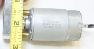
Info found on motor:
12 VDC MOTOR
Mabuchi # RS-555VD.
12Vdc, 750mA (no-load).
Operates over 8-18 Vdc range.
38.5mm diameter x 65mm long.
3.17mm (1/8") diameter shaft. Solder lug / 0.18" qc terminals.
CAT# DCM-354
$3.50 each
From http://www.scribd.com/doc/66758727/42/DC-MOTORS page 79
In order to get something going on the belts, I ordered:
Products
------------------------------------------------------
2 x 3/16" (4.8mm) Orange 83A O-ring Belt = $8.00
	Cut-Length 5
2 x 3/16" (4.8mm) Orange 83A O-ring Belt = $7.78
	Cut-Length 5.5
2 x 3/16" (4.8mm) Orange 83A O-ring Belt = $7.86
	Cut-Length 5.3125
2 x 5/32" (4mm) Clear 83A O-ring Belt = $7.10
	Cut-Length 5.25
------------------------------------------------------
from Ebelting.com
Oct 28 Mike L
Working to figure out which belt to acquire.
The durabelt people have a calculator for spec'ing out a belt at http://durabelt.com/beltlengthcalculator.php. Method three seems the most promising given the measurements Chris and I took.
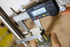
After two pages of trying to work out the math, I came up with a length of 146.35mm (5.76181") for the unstretched length, durabelts calculator gave me the same thing (if I said 0 percentage stretch.
Still not sure if I have this right though. The belt vender sells belts in 1/16" increments.
Oct 26 2012 - Mike L
Zenbot has been moved to a desk in the front (broadway facing door) room.
It is missing one of the rubber feet (that might have been added aftermarket). May be easiest to just replace all four - the three that are still on are clearly "stick on" type. There is no special size or shape required.
PC originally wouldn't boot. Chris P. futzed with the ram in the machine (added/removed/cleaned-with-eraser) and the machine became willing to boot.
Once machine was booting the EMC2/linuxcnc?/axis-software was willing to run, and upon turning on the X,Y,Z controller, the software would drive the armature.
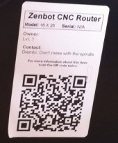
The machine is sitting with its orignal QR code facing out, this seem to be a good way point it so-as to have the x driver-motor pointing out at the user as it slides left to right BUT the config on the machine currently has both x and y configured for the machine rotated 180 degrees. I'm working to understand the config, with the expectation that I'm going to reverse both the x and the y (the z is fine)
Also critically important, all the axis are WAY out of scale. Moving the head 1.4 inches in the controlling software really moves the head very rapidly 10 inches in real space. Given the machine only has 10-20 inches of travel on x and y this makes a really easy to crash the head into the end of the rails its mounted on. Given the machine has no sensors for the end of the rails, if the software commands it there it will simply slam the head into the rails and grind the motors trying to keep moving on. (specifically moving 10" in real space read 1.3892" on the software, moving the head 10" on the y axis in real space read as 1.3762" on the software, z wasn't measured)
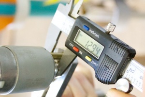
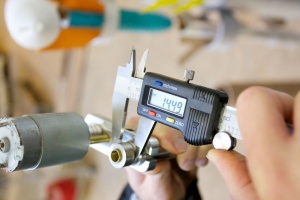
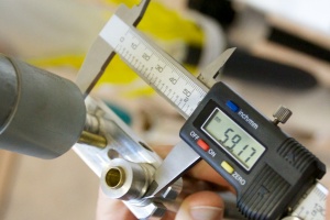
To the right are pictures of measurements of the spindle belt groves, with the goal of computing what size belt we need to acquire
Chris found a "O ring style belt" custom belt maker. dura-belt durabelt.com is the manufacture, but they don't sell retail. ebelting.com is one of the retails for them.
--
Chris Pettus did some googling and found another zenbot user using a Wolfgang spindle and powering it with a computer power supply: https://plus.google.com/103014027224354212001/posts/9EELxYozG4W
Oct 25 2012 - Mike L
In a back-and-forth with Chorgy he said: "The spindle I ran using a generic 13v regulated bench top that I bought from radio shack for like $30-$40." Which I'm somewhat unclear if he donated but regardless is not in the pile of equipment with the Zenbot.
Chorgy also added that he really can't see the motor drawing more then 20A 12v dc max (.. through the motor controller board) and so he though a computer power supply would work.
Oct 24 2012 - Mike L
Warped photo of the QR code that attached to the Zenbot
Oct 23 2012 - Mike L
Following up on what I found out about the zenbot:
- Chris connected me to Gerrit, he is the writer of the note (that I sent earlier) on the zenbot and seems to be on top of what needs to be done to get it going. (I.E. he does "have the ball")
- Current status
- Believed capable of high precision operation other then a non-operating spindle (the router part) because of multiple missing parts, and likely incompletely configured control software.
- Parts needed to get the zenbot operating:
- Power supply for the spindle motor
- either found by chorgy or an expense of $75-150
- Belts for spindle
- Gerrit had an exchange with Wolfgang Eng (maker of the spindle part) and thinks he may have enough info to order from a parts house (price currently unknown, though expected to be low)
- More bits (there is one with the zenbot now)
- Both Gerrit and chorgy agree that ebay is the way to go. Gerrit's comment was that the reason that ebay bits are so cheap is because they are partly used and have become slightly out of dimensional spec. With effort, the bits can be re-measure there-by enabling them to be used at full precision.
- Config for EMC2? (x,y,z stepper motor control software)
- The current assumption is that the EMC2 on the linux box doesn't have a fully configured config for the zenbot. Gerrit has contacted the zenbot and they have said they will send him a (customer supplied) EMC2 config, though they haven't yet so he is planning on bugging them again.
- Brian W posted that he had x,y,z working a few months back, Brian if you think the config is complete then please reply so Gerrit doesn't have to keep hassling the zenbot folks
- Power supply for the spindle motor
If the zenbot gets up and running, there are number of improvement that Gerrit is already thinking about ("stops" to calibrate the arms - likely requiring a different controller, enclosure for the control systems, vacuum system, etc..)
The consensus seems to be that machine is in good shape, and should really be capable of high accuracy milling if the parts/config are done and the machine is treated gently.
I have some extra time over the next few weeks and I'm going to try and help Gerrit move things forward, I suspect that may not be enough to get the system operational, but if nothing else I'll make sure to document what happens.
Pre Oct 20 2012
Had written notes from Gerrit:
