Screaming Bread: Difference between revisions
| Line 9: | Line 9: | ||
= Intended Victim = | = Intended Victim = | ||
[http://firstbuild.com 1st Build] | == [http://firstbuild.com 1st Build] == | ||
= The Basics = | = The Basics = | ||
Revision as of 22:31, 23 September 2015
The Idea
Louisville Mini Maker Faire was an opportunity for LVL1 and 1st Build have a little fun. So, LVL1 decided to play a prank. 1st Build had a refrigerator on display. The door would open and close during the event. When the door opens, the light goes on inside. So, what if when the door opened and the light went on inside, a loaf of bread screamed.
Conspirators
David Jokinen - LVL1 Member - Original idea and bread stuffer
Undisclosed - Member of the Truly Mad Scientist's LVL1 Splinter Group - Electronics and bad advice
Intended Victim
1st Build
The Basics
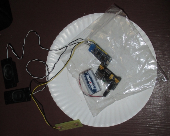
A loaf of Bread
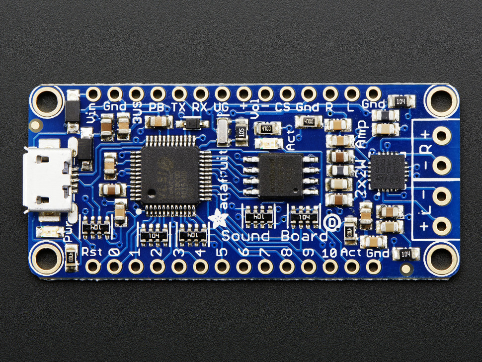
AdaFruit FX Sound Board
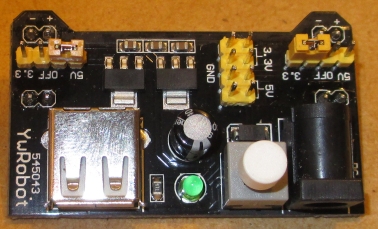
5v Power Supply
CDS sensor
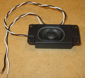
Speaker
Recorded screams
Wiring
Power
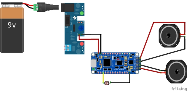
A 5/3.3 volt power supply is located.
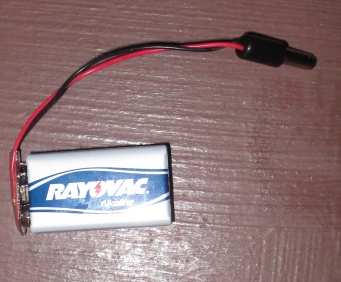
The power supply will use a 9 volt battery. A barrel connector compatible with the power supply board is added to a 9v battery connector.
Light Trigger
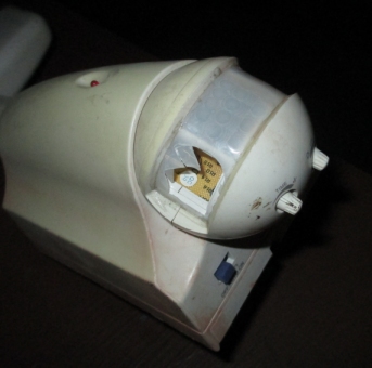
First, we located a CDS cell. One was found in a motion detection sensor with a broken cover window.
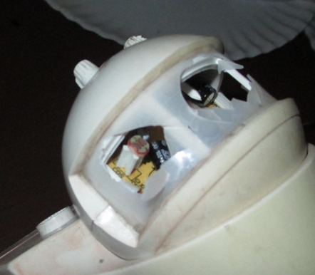
Breaking the cover window even more exposed the CDS cell.
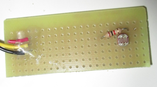
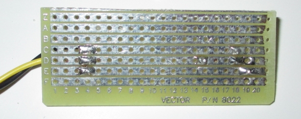
Next came removal and placement on a piece of PCB.
At first, it was thought that an external pull up resistor was needed to trigger the FX board. But the FX board had internal pull up resistors, so the added resistor was not necessary. Two wires were attached and the CDS sensor was ready.
Putting the Electronics Together
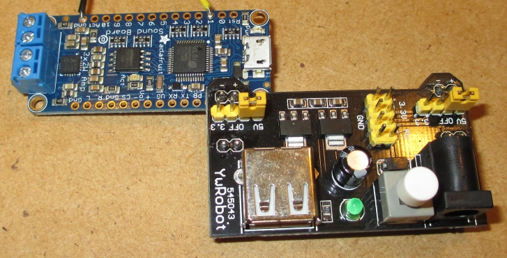
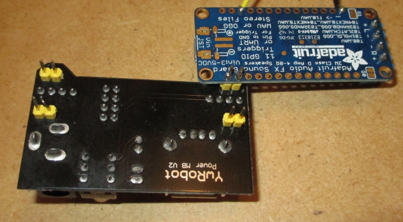
The assembly of the unit begins with connecting the power supply and FX Board. The pin alignment of the power supply and FX Board power terminals allows the two boards to be soldered together directly. Next the CDS Sensor is soldered to trigger line 1.
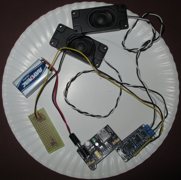
Final assembly of the electronics is completed by wiring in the speakers and connecting the battery pack to the power supply.
Sanitary Consideration
To prevent contamination, the electronics are properly baggied.
Bread
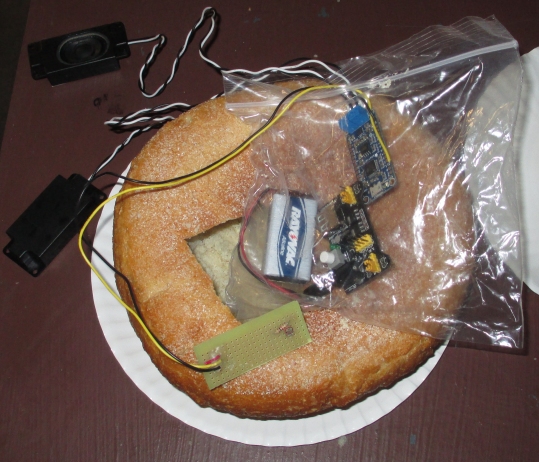
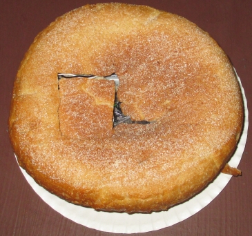
Next, a loaf of bread is hollowed out and the stuffing begins.
The Sensor is stuffed in first, followed by the electronic baggy.
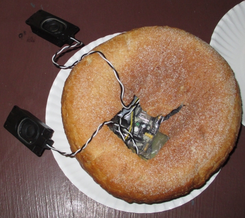
The Speakers are stuffed in last.
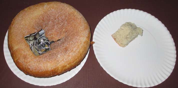
The entrance to the bread is sealed with a plug and the bread is ready to scream when exposed to light.
What Happened
The best laid plans did not work out. Access to the fridge was blocked. No joy.
Now What
Halloween is coming. Maybe another opportunity will arise.
Considerations for the future include:
Fake Bread
Power supplied via USB Hub installed in 1st Build's Refrigerator.
