3rd Inning: Difference between revisions
Jump to navigation
Jump to search
No edit summary |
|||
| Line 1: | Line 1: | ||
__NOTOC__ | |||
==Introduction== | ==Introduction== | ||
'''Tri-color LED fading''' | '''Tri-color LED fading''' | ||
Revision as of 20:04, 17 May 2010
Introduction
Tri-color LED fading
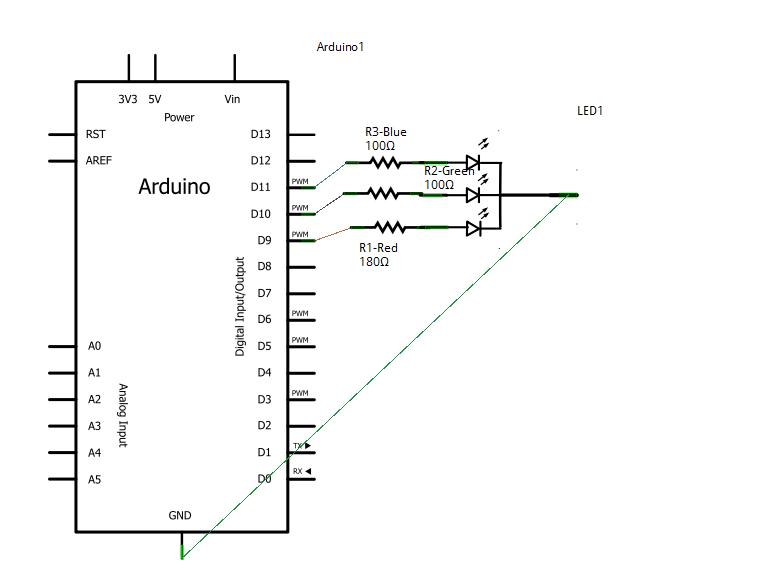
This is the way to hook up a tri-color LED. Basically you are hooking up 3 leds that have a common ground. The average voltage that each led uses to power itself is varied using pulse width modulation. The code basically does a neato nested loop to vary the colors. This is a fun circuit to play with. Make sure to use the resistors or you may burn up your LED - The cost a couple of bucks!
Components Needed
- Freeduino or Arduino or clone
- USB cable for Freeduino
- Freeduino development software - download here!
- Solderless Breadboard
- Hookup wire 22gauge solid
- Common Cathode LED
How to
- refer to the fritzing drawing to place the wires
- upload the code below using cut and paste
- Run and watch the fading of the led!
Schematic
Fritzing
Code
Cut and paste this into your Arduino code window!
int RED = 9;    // RED pin of the LED to PWM pin 9
int GREEN = 10;  // GREEN pin of the LED to PWM pin 10
int BLUE = 11;   // BLUE pin of the LED to PWM pin 11

void setup()
{
  // nothing for setup
}

void loop()
{
  for(int r = 0; r < 1024; r+=5) {
    for(int g = 0; g < 1024; g+=5) {
      for(int b = 0; b < 1024; b+=5) {
        analogWrite(RED, r);
        analogWrite(GREEN, g);
        analogWrite(BLUE, b);
        delay(30);
      }
    }
  }
}
or cut and paste this one... it is neater
//This code comes from...
//http://www.arduino.cc/cgi-bin/yabb2/YaBB.pl?num=1207331496
//modified to just go through a pretty color loop!
//use tools->serial monitor to watch the values
//bpw 5/10/10


int rpin = 9;    // RED pin of the LED to PWM pin 9
int gpin = 10;  // GREEN pin of the LED to PWM pin 10
int bpin = 11;   // BLUE pin of the LED to PWM pin 11

int r=0, g=0, b=0;
float h;


void h2rgb(float h, int &R, int &G, int &B);

void setup()                    // run once, when the sketch starts
{
   Serial.begin(9600);
}


void loop()                     // run over and over again
{

  for (int val = 0; val <1024; val++) {
    h = ((float)val)/1024;

    h2rgb(h,r,g,b);
    Serial.println (val) ;
    Serial.println (h) ;
    Serial.println (r) ;
    Serial.println (g) ;
    Serial.println (b) ;
    Serial.println ("  ") ;

    analogWrite(rpin, r);
    analogWrite(gpin, g);
    analogWrite(bpin, b);
    //delay(50);
  }
}

void h2rgb(float H, int& R, int& G, int& B) {

  int var_i;
  float S=1, V=1, var_1, var_2, var_3, var_h, var_r, var_g, var_b;

  if ( S == 0 )                       //HSV values = 0 ÷ 1
  {
    R = V * 255;
    G = V * 255;
    B = V * 255;
  }
  else
  {
    var_h = H * 6;
    if ( var_h == 6 ) var_h = 0;      //H must be < 1
    var_i = int( var_h ) ;            //Or ... var_i = floor( var_h )
    var_1 = V * ( 1 - S );
    var_2 = V * ( 1 - S * ( var_h - var_i ) );
    var_3 = V * ( 1 - S * ( 1 - ( var_h - var_i ) ) );

    if      ( var_i == 0 ) {
      var_r = V     ;
      var_g = var_3 ;
      var_b = var_1 ;
    }
    else if ( var_i == 1 ) {
      var_r = var_2 ;
      var_g = V     ;
      var_b = var_1 ;
    }
    else if ( var_i == 2 ) {
      var_r = var_1 ;
      var_g = V     ;
      var_b = var_3 ;
    }
    else if ( var_i == 3 ) {
      var_r = var_1 ;
      var_g = var_2 ;
      var_b = V     ;
    }
    else if ( var_i == 4 ) {
      var_r = var_3 ;
      var_g = var_1 ;
      var_b = V     ;
    }
    else                   {
      var_r = V     ;
      var_g = var_1 ;
      var_b = var_2 ;
    }

    R = (1-var_r) * 255;                  //RGB results = 0 ÷ 255
    G = (1-var_g) * 255;
    B = (1-var_b) * 255;
  }
}
Troubleshooting
- is your led in correctly (the longest pin(cathode) should connect to ground)
- code for the pins on Arduino correct
Resources
Most of this example is from http://wiring.org.co/learning/basics/rgbled.html.
A great thread on hue controlled tri-colored LEDs is here... http://www.arduino.cc/cgi-bin/yabb2/YaBB.pl?num=1207331496

