Coffin Tester: Difference between revisions
No edit summary |
|||
| (138 intermediate revisions by the same user not shown) | |||
| Line 1: | Line 1: | ||
=Coffin Tester= | |||
[[File:JAC Cacphony.jpg|top|left]] | |||
[[File:JAC Coffin Tester.jpg|top|right]] | |||
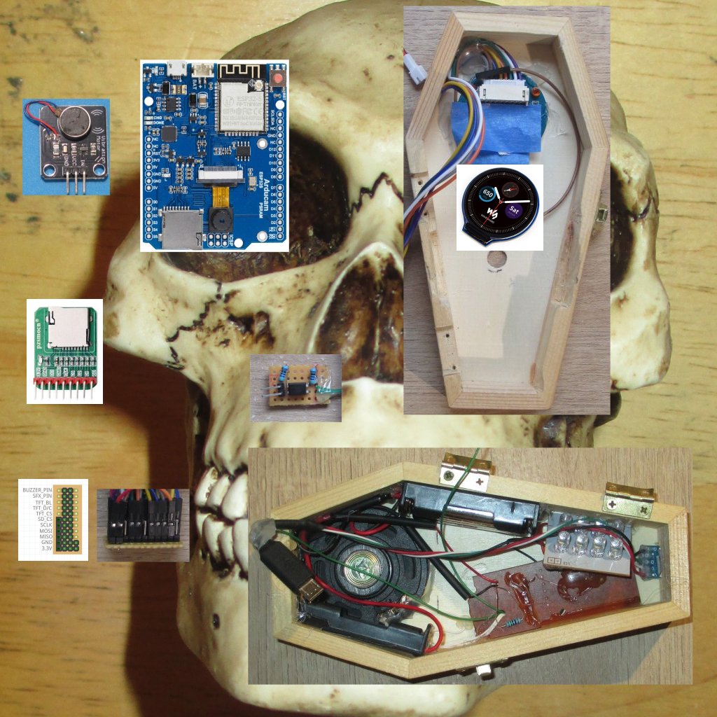
=Prelude To The Madness= | |||
What better project to resurrect from the incomplete project pile then “The Coffin Tester”? This project was inspired by the chance encounter of a small wooden coffin at a hobby store. With a coffin comes the standard project ideas: Someone is trying to get out or someone is inviting you in. Making both projects at once was my decision. | |||
=Overview from 6ft Under= | |||
The embedded coffin display in the lid shows classic monster portraits, letting you know who is inside. However, the camera in the lid also takes images of the viewer. When it detects a face, it displays the image on the display, letting you know that you are inside now. A Halloween SFX module within the box fires up and horror ensues. The WiFi capable board within makes future upgrades to functionality possible. The horror never ends. | |||
=Part Selection= | =Part Selection= | ||
==ArduCam ESP32S Uno w/ PSRAM | |||
{|class="wikitable" | |||
!colspan="5"| Parts | |||
|- | |||
|Name | |||
|Image | |||
|Details | |||
|Considerations | |||
|- | |||
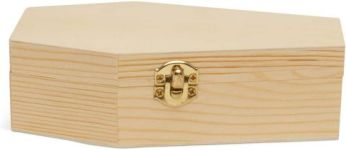
|Small Wooden Coffin | |||
|[[File:JAC_Coffin.jpg|left|thumbnail|x150px]] | |||
| | |||
* Small Body Storage | |||
* Cheap and Wooden | |||
| | |||
* Just another item to put me on a watch list | |||
|- | |||
|ArduCam ESP32S Uno w/ PSRAM | |||
|[[File:JAC_ArduCam_ESP32S_Uno_with_PSRAM.jpg|left|thumbnail|x150px]] | |||
| | |||
* OV2640 Camera | * OV2640 Camera | ||
* ESP32S | * ESP32S | ||
* WiFi | * WiFi | ||
* BLE | * BLE | ||
* SD MMC | * SD MMC | ||
| | |||
* Based on AI-Thinker ESP32 Camera Configuration and hardware setup | * Based on AI-Thinker ESP32 Camera Configuration and hardware setup | ||
* Discontinued hardware, so time to use. | * Discontinued hardware, so time to use. | ||
* | * RIP | ||
|- | |||
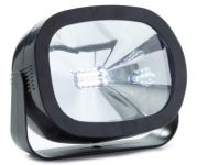
|SFX Halloween Module | |||
|[[File:JAC_SFX_Module_Front.jpg|left|thumbnail|x150px]] | |||
| | |||
* Sound and LED Sequences | * Sound and LED Sequences | ||
* Strobe Function | * Strobe Function | ||
* Sound/Vibration Activation | * Sound/Vibration Activation | ||
* Demo Button | * Demo Button | ||
| | |||
* Prebuilt Unit | |||
* Already themed for coffin themed project | |||
|- | |||
|Round Display | |||
|[[File:JAC_TFT_GC9A01A_Front.jpg|left|thumbnail|x150px]] | |||
| | |||
* 1.28 inch LCD Module | |||
* 240 x 204 Pixels | |||
* GCA901A Controller | |||
| | |||
* Realistic Corpse Viewing Port | |||
|- | |||
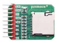
|SD Card Adapter | |||
|[[File:JAC_SD_Card_Adapter_Front.jpg|left|thumbnail|x150px]] | |||
| | |||
* Micro SD Storage Board | |||
* SPI Interface | |||
| | |||
* In order to free up GPIO Pins for interfacing to the display, the onboard SD_MMC is disabled and this adapter provides SD access. | |||
|- | |||
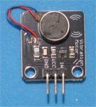
| Buzzer | |||
| | |||
[[File:JAC Coffin Buzzer.jpg|left|thumb|x150px]] | |||
| | |||
Vibrating Motor | |||
| | |||
Add a little buzz. | |||
|- | |||
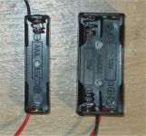
|Battery Holders | |||
|[[File:JAC_AAA_Battery_Holders.jpg|left|thumbnail|x150px]] | |||
| | |||
* 1 AAA Cell | |||
* 2 AAA Cells | |||
| | |||
* Volume Issues lead to use of two holders instead of a single 3 AAA cell holder | |||
* 2 AA Holder used was not messed up like the one in this photo. | |||
|- | |||
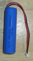
|ICR18650 Battery | |||
|[[File:JAC_ICR18650.jpg|left|thumbnail|x200px]] | |||
| | |||
* 2200mAh | * 2200mAh | ||
* 3.7V | * 3.7V | ||
| | |||
* Had one lying around | |||
|- | |||
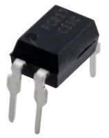
|PC817 Optocoupler | |||
|[[File:JAC_PC817.jpg|left|thumbnail|x200px]] | |||
| | |||
* Low Voltage Trigger | |||
* 5kVolts of Isolation | |||
| | |||
* Provides an electrically isolated trigger signal for the Halloween SFX Module | |||
|- | |||
| Micro USB Cable | |||
| [[File:JAC Coffin Micro USB Cable.jpg|left|thumbnail|x200px]] | |||
| | |||
* Plutonium Implosion Device | |||
* 18.6 kilotons | |||
| | |||
* Relatively Small | |||
* Had one lying around | |||
|- | |||
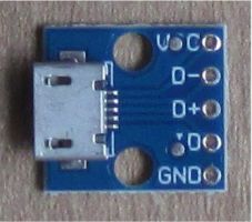
| Micro USB Port Adapter Board | |||
| [[File:JAC Micro USB Adapter Board.jpg|left|thumbnail|x200px]] | |||
| | |||
* Micro USB | |||
| | |||
* Allows access for power, programming and charger for internal battery | |||
|} | |||
==Additional Stuff== | |||
{|class="wikitable" | |||
!colspan = "2"| Materials | |||
|- | |||
| Jumper Wires Female/Female | |||
| Plastic Fork | |||
|- | |||
| Strip Board | |||
| Painter's Tape | |||
|- | |||
| Header Pins Male | |||
| Hot Glue | |||
|- | |||
| Header Pins Female | |||
| Borated Paraffin | |||
|- | |||
| Electrical Tape | |||
| | |||
|- | |||
| Heat Shrink Tubing | |||
| | |||
|} | |||
=Element Preparation= | |||
{|class="wikitable" | |||
!colspan="5"| Elements | |||
|- | |||
|Halloween SFX Module | |||
|ArduCam ESP32S Uno w/ PSRAM | |||
|Coffin Top | |||
|Coffin Bottom | |||
|- | |||
| | |||
* Front Shell – (Not Used) | |||
* Reflector – (Not Used) | |||
* High Brightness LED 2x4 Matrix | |||
* Circuit Board Assembly | |||
** PCB | |||
** Function Switch – (Removed) | |||
** Strobe Speed Potentiometer – (Removed) | |||
* Speaker | |||
* Piezo Disk – (Not Used) | |||
* Demo Button – (Not Used) | |||
* Back Shell with integrated Battery Holder – (Not Used) | |||
* Battery Cover – (Not Used) | |||
| | |||
* Right Angle Inward Facing Male Header Pins on Underside | |||
* Spacers Mounted on USB End of Board | |||
| | |||
* 1.25" Upper End Hole for Round Display View | |||
* 3/8" Lower Mid Section Hole for Camera View Port | |||
* Inside Inner Edge Carve Outs for ArduCam Board Mounting | |||
* Inside Bottom Edge Carve Out for Custom Bus Board Mounting | |||
| | |||
* Micro USB Access Slot in Bottom End | |||
* Two Small Holes for Micro USB Socket Adapter Mounting | |||
|} | |||
=Assemblies= | |||
==Block Diagram of Project Elements== | |||
[[File:JAC Coffin Block Diagram.jpg]] | |||
*Not in image: A Buzzer was added later to Coffin top. | |||
==Coffin Top Assembly== | |||
{|class="wikitable" | |||
!colspan="5"| Coffin Top | |||
|- | |||
|[[File:JAC Coffin Top Unpacked Wired 2.jpg|left|thumb|x200px]] | |||
|[[File:JAC Coffin Top Unpacked Wired.jpg|left|thumb|x200px]] | |||
|[[File:JAC Coffin Top Packed.jpg|left|thumb|x200px]] | |||
|[[File:JAC Coffin Top with Holes.jpg|left|thumb|x200px]] | |||
|[[File:JAC Coffin GPIO Usage.jpg|left|thumb|x200px]] | |||
|} | |||
===Construction=== | |||
* The main constraint on the build is volume of the Coffin. If only the functions of the ArduCam, Display, SD Card and Buzzer were implemented then space is not an issue. But, addition of additional functions lead to the decision to ensure that all the Coffin Top functions would be implemented within the volume of the Coffin Top. | |||
* The access for power and programming in-place resulted in a USB cable extension capability. This would represent one of the connections between Top and Bottom of Coffin. The inclusion of a Battery charger on the ArduCam meant that a battery could be used to conveniently power the project. This is the second Top/Bottom connection. The SFX Module trigger is the third. | |||
== | ===PIN Consideration=== | ||
* GPIO 33 - This pin is available on the ArduCam but not on the ESP32Cam which is why the ESP32Cam can be substituted for the ArduCam with the sacrifice of a GPIO Pin and therefore a function. My suggestion would be to sacrifice the Buzzer and reassign Pins. | |||
* GPIO 15, 14, 13 and 12 - This is the standard HSPI Pin assignment on an ESP32. For the ArduCam and ESP32Cam, the onboard SD MMC uses these pins for accessing the SD Card in MMC mode, as well as GPIO 02 and 04. The need for a TFT Display SPI connection is why it is disabled. A SD Card in SPI mode can then be reintegrated into the design. | |||
* GPIO 04 and 02 - These Pins are freed up by disabling SD MMC and are available for project use. See Project Surprises Section for GPIO 02 surprise. | |||
* GPIO 03 and 01 - These are the RX and TX pins. Use of these Pins later in the project can not Pull-Down the Pins as it would interfere with Boot-Up. During software debugging, the RX can be used if serial input is not needed and serial.print can be used to debug and monitor activity. When all the debugging is done, do not use any serial interaction with the monitor and the TX pin is available. However, upon startup/boot the device automatically sends out messages via the TX. So be prepared for the signals on the TX/GPIO 01 Pin. For my implementation, I assigned the buzzer function therefore the project buzzes upon start up. | |||
== | ==Coffin Bottom Assembly== | ||
* | [[File:JAC Coffin Bottom Packed.jpg|left]] | ||
* 2 | |||
===Construction=== | |||
* Well, my decision to document was before my decision to pack it in and glue it down. The primary issues here are space and interface with the Coffin Top circuitry. | |||
* The arrangement of contents needs to accommodate the inclusion of a ICR18650 battery. The battery is a late idea for the project and has not been vetted for safety. So, don't do it. Think of the horror of the device bursting in an explosion of fire and chemicals. Don't!!! | |||
==Interconnection Assemblies== | |||
{|class="wikitable" | |||
!colspan="2"| Interconnectors | |||
|- | |||
|Part | |||
|Design | |||
|- | |||
| [[File:JAC Coffin Wired Interface Bus.jpg|left|thumb|x200px]] | |||
| [[File:JAC Coffin Interface Bus.jpg|left|thumb|x200px]] | |||
|- | |||
| [[File:JAC Coffin Optocoupler Interface.jpg|left|thumb|x200px]] | |||
| [[File:JAC Coffin Optocoupler SFX Trigger Circuit.jpg|left|thumbnail|x200px]] | |||
|} | |||
== | ===Construction=== | ||
* | * The Coffin Wired Interface can be abandon for permanent wire soldering and save space. But this was a build and experiment. The jumper wires allows for testing and Pin re-assignment. | ||
* | * The Optocoupler is routine for isolating devices with different voltages, current issues, power supplies and signal interference. | ||
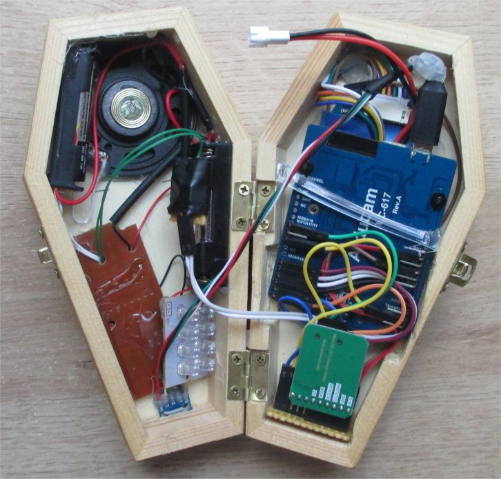
== | ==Assembled== | ||
[[File:JAC Coffin Opened Complete.jpg]] | |||
The most time consuming element of the project was packing the coffin. The parts easily fit but all the wiring gets in the way. | |||
*Not in photo: A Buzzer was added later to Coffin top. | |||
Coffin | |||
=Project Surprises:= | =Project Surprises:= | ||
GPIO02 boot-up tests for PSRAM voltage requirement interfered with | * GPIO02 boot-up tests for the PSRAM voltage requirement and interfered with startup. Required eFuse setting to permanent PSRAM voltage level for normal operation | ||
ESP32 Cam with AI-Thinker hardware setup can be used for the project with a simple pin assignment change. | * ESP32 Cam with AI-Thinker hardware setup can be used for the project with a simple pin assignment change and the creators choice of one function loss. | ||
An overly elaborate method for using a vibrating motor to trigger SFX module, isolating the module electrically from Microcontroller abandon due to unnecessary complexity and stray triggering from handling project. | * An overly elaborate method for using a vibrating motor to trigger SFX module, isolating the module electrically from Microcontroller abandon due to unnecessary complexity and stray triggering from handling project. | ||
SFX module uses High Brightness LEDs that cause short bursts of high current that have to be | * SFX module uses High Brightness LEDs that cause short bursts of high current that have to be handled by separate battery pack in order to not require additional power supply circuitry for a common power supply. | ||
I had a ICR18650 lying around, so battery operation of project utilizing built in charging of the ArduCam. Then again, it could be a self-destruct method. | * I had a ICR18650 lying around, so battery operation of project utilizing built in charging of the ArduCam. Then again, it could be a self-destruct method. | ||
* Had to pin down ArduCam board in coffin, so I used a piece of a plastic fork. | |||
=Programming Elements= | =Programming Elements= | ||
TFT display for the ArduCam | * TFT display for the ArduCam | ||
HSPI usage | * HSPI usage | ||
Facial Detection Code | * Facial Detection Code | ||
Simple RAW Image decoding for saved images | * Simple RAW Image decoding for saved images | ||
Camera image buffer display to TFT display | * Camera image buffer display to TFT display | ||
=Demonstration Video= | |||
[https://youtu.be/eD2yRS7119s Demo Video] | |||
=Resource= | |||
{|class="wikitable" | |||
!colspan="2"| Parts | |||
|- | |||
|Item | |||
|Link | |||
|- | |||
| ArduCam Product Page | |||
| https://www.arducam.com/product/b0192-arducam-iotai-esp32-uno-psram-ov2640-camera/ | |||
|- | |||
| GCA901A Demo on ESP32 | |||
| https://github.com/talofer99/ESP32CAM-Capture-and-send-image-over-esp-now | |||
|- | |||
| ESP32 SPI Information | |||
| https://randomnerdtutorials.com/esp32-spi-communication-arduino/ | |||
|- | |||
| ESP32 Now | |||
| https://randomnerdtutorials.com/esp-now-two-way-communication-esp32/ | |||
|- | |||
| ESP32 Cam Photo Webserver | |||
| https://randomnerdtutorials.com/esp32-cam-take-photo-display-web-server/ | |||
|- | |||
| ESP32 Cam Selfie | |||
| https://robotzero.one/esp32-cam-tft-selfie/ | |||
|- | |||
| ESP32 Cam Pinout Guide | |||
| https://randomnerdtutorials.com/esp32-cam-ai-thinker-pinout/ | |||
|- | |||
| ESP32 Cam Settings Guide | |||
| https://randomnerdtutorials.com/esp32-cam-ov2640-camera-settings/ | |||
|- | |||
| ESP32 Cam as Camera with Display | |||
| https://www.instructables.com/ESP32-ESP32-CAM-With-OV2640-Using-SIPHSPI-for-TFT-/ | |||
|- | |||
| ESP32 Camera and Webserver Sample Program from hardware library | |||
| Ardunio IDE Library | |||
|- | |||
| ESP-DL | |||
| https://github.com/espressif/esp-dl | |||
|} | |||
===Notes=== | |||
* Seldom does a single link hold all the information needed for a project. | |||
* These represent the different paths taken while researching the basic ESP32, Display integration and face detection. | |||
=Code= | |||
* The code is a splicing of several programs and samples. See the Resource Section. | |||
* The post_Error function is a placeholder for an expected ESP_NOW functionality and is to serve for simple message broadcast. | |||
==Includes== | |||
<nowiki> | |||
#include <SPI.h> | |||
#include "FS.h" | |||
#include <SD.h> | |||
#include "Adafruit_GFX.h" | |||
#include "Adafruit_GC9A01A.h" | |||
#include "esp_camera.h" | |||
#include "esp_timer.h" | |||
#include "human_face_detect_msr01.hpp" | |||
#include "human_face_detect_mnp01.hpp" | |||
</nowiki> | |||
==Defines== | |||
<nowiki> | |||
// Pin definition for CAMERA_MODEL_AI_THINKER | |||
#define PWDN_GPIO_NUM 32 | |||
#define RESET_GPIO_NUM -1 | |||
#define XCLK_GPIO_NUM 0 | |||
#define SIOD_GPIO_NUM 26 | |||
#define SIOC_GPIO_NUM 27 | |||
#define Y9_GPIO_NUM 35 | |||
#define Y8_GPIO_NUM 34 | |||
#define Y7_GPIO_NUM 39 | |||
#define Y6_GPIO_NUM 36 | |||
#define Y5_GPIO_NUM 21 | |||
#define Y4_GPIO_NUM 19 | |||
#define Y3_GPIO_NUM 18 | |||
#define Y2_GPIO_NUM 5 | |||
#define VSYNC_GPIO_NUM 25 | |||
#define HREF_GPIO_NUM 23 | |||
#define PCLK_GPIO_NUM 22 | |||
#define SPI_MOSI 13 | |||
#define SPI_MISO 12 | |||
#define SPI_CLK 14 | |||
#define SPI_SS 15 | |||
#define TFT_DC 33 // Data Command control pin | |||
#define TFT_CS 15 // Chip select control pin | |||
#define TFT_RST -1 | |||
#define TFT_BL 3 | |||
#define SD_CS 4 | |||
#define SFX_MODULE_PIN 2 | |||
#define BUZZER_PIN 1 | |||
#define TFT_ROTATION 0 // 0 to 3 | |||
</nowiki> | |||
==Initializations== | |||
<nowiki> | |||
SPIClass MySPI(HSPI); // Declare an HSPI bus object (to use or BOTH TFT and SD-card) | |||
Adafruit_GC9A01A tft(&MySPI, TFT_DC, TFT_CS); | |||
boolean camera_ok; | |||
boolean InitSD() | |||
{ | |||
boolean success=SD.begin(SD_CS,MySPI); | |||
if (!success) | |||
{ | |||
post_Error("Fail: check formatted SD-card is in!"); | |||
return false; | |||
} | |||
listDir(SD, "/", 0); | |||
return success; | |||
} | |||
boolean camera_init() | |||
{ | |||
camera_config_t config; | |||
config.ledc_channel = LEDC_CHANNEL_0; | |||
config.ledc_timer = LEDC_TIMER_0; | |||
config.pin_d0 = Y2_GPIO_NUM; | |||
config.pin_d1 = Y3_GPIO_NUM; | |||
config.pin_d2 = Y4_GPIO_NUM; | |||
config.pin_d3 = Y5_GPIO_NUM; | |||
config.pin_d4 = Y6_GPIO_NUM; | |||
config.pin_d5 = Y7_GPIO_NUM; | |||
config.pin_d6 = Y8_GPIO_NUM; | |||
config.pin_d7 = Y9_GPIO_NUM; | |||
config.pin_xclk = XCLK_GPIO_NUM; | |||
config.pin_pclk = PCLK_GPIO_NUM; | |||
config.pin_vsync = VSYNC_GPIO_NUM; | |||
config.pin_href = HREF_GPIO_NUM; | |||
config.pin_sscb_sda = SIOD_GPIO_NUM; | |||
config.pin_sscb_scl = SIOC_GPIO_NUM; | |||
config.pin_pwdn = PWDN_GPIO_NUM; | |||
config.pin_reset = RESET_GPIO_NUM; | |||
config.xclk_freq_hz = 20000000; | |||
config.pixel_format = PIXFORMAT_RGB565; | |||
if (psramFound()) | |||
{ // larger bufer | |||
config.frame_size = FRAMESIZE_QVGA; | |||
config.jpeg_quality = 2; | |||
config.fb_count = 2; | |||
config.grab_mode = CAMERA_GRAB_LATEST; | |||
} | |||
else | |||
{ // smaller buffer | |||
config.frame_size = FRAMESIZE_QVGA; | |||
config.jpeg_quality = 12; | |||
config.fb_count = 1; | |||
} | |||
esp_err_t err = esp_camera_init(&config); | |||
if (err != ESP_OK) | |||
{ | |||
post_Error("Camera init failed with error: "+String(err)); | |||
return false;; | |||
} | |||
sensor_t * s = esp_camera_sensor_get(); | |||
s->set_hmirror(s, 1); // 0 = disable , 1 = enable | |||
s->set_vflip(s, 1); // 0 = disable , 1 = enable | |||
return true; | |||
} | |||
</nowiki> | |||
==Core== | |||
<nowiki> | |||
void setup() | |||
{ | |||
delay(200); | |||
pinMode(BUZZER_PIN,OUTPUT); | |||
pinMode(TFT_CS,OUTPUT); | |||
pinMode(SD_CS,OUTPUT); | |||
pinMode(SFX_MODULE_PIN,OUTPUT); | |||
analogWrite(TFT_BL,255); | |||
tft.begin(); | |||
tft.setRotation(TFT_ROTATION); | |||
tft.setTextColor(GC9A01A_WHITE); | |||
tft.setTextSize(2); | |||
tft_clear(); | |||
tft.println("Hello World"); | |||
InitSD(); | |||
camera_ok=camera_init(); | |||
if (!camera_ok) post_Error("but without Camera"); | |||
delay(1000); | |||
randomSeed(analogRead(0)); | |||
} | |||
void loop() | |||
{ | |||
int face_test = 0; | |||
int loop_count = 25; | |||
tft_clear(); | |||
TFT_fade(-1,10); | |||
display_randon_sd_raw(); | |||
TFT_fade(1,10); | |||
for(int x = 0; x < loop_count; ++x) | |||
{ | |||
if (xcapture_handler(&face_test) == 100) | |||
{ | |||
buzzer_zap(200); | |||
SFX_Module_Fire(); | |||
delay(5000); | |||
x = loop_count; | |||
} | |||
} | |||
} | |||
</nowiki> | |||
==Display Functions== | |||
<nowiki> | |||
void tft_clear() | |||
{ | |||
tft.fillScreen(GC9A01A_BLACK); | |||
tft.setCursor(0,0); // top | |||
} | |||
void TFT_fade(int fade_type, int fade_delay) | |||
{ | |||
switch (fade_type) | |||
{ | |||
case 1: | |||
for(int x=0;x<256;++x) | |||
{ | |||
analogWrite(TFT_BL,x); | |||
delay(fade_delay); | |||
} | |||
break; | |||
case -1: | |||
for(int x=255;x>-1;--x) | |||
{ | |||
analogWrite(TFT_BL,x); | |||
delay(fade_delay); | |||
} | |||
analogWrite(TFT_BL,0); | |||
analogWrite(TFT_BL,0); | |||
analogWrite(TFT_BL,0); | |||
break; | |||
} | |||
delay(fade_delay); | |||
} | |||
</nowiki> | |||
==Stored Image Functions== | |||
<nowiki> | |||
String picture_gallery[64]; | |||
int picture_gallery_size = 0; | |||
void listDir(fs::FS &fs, const char * dirname, uint8_t levels) | |||
{ | |||
File root = fs.open(dirname); | |||
if (!root) | |||
{ | |||
post_Error("Failed to open directory"); | |||
return; | |||
} | |||
if (!root.isDirectory()) | |||
{ | |||
post_Error("Not a directory"); | |||
return; | |||
} | |||
File file = root.openNextFile(); | |||
while(file) | |||
{ | |||
if (file.isDirectory()) | |||
{ | |||
if (levels) | |||
{ | |||
listDir(fs, file.name(), levels -1); | |||
} | |||
} | |||
else | |||
{ | |||
picture_gallery[picture_gallery_size] = file.name(); | |||
++picture_gallery_size; | |||
} | |||
file = root.openNextFile(); | |||
} | |||
} | |||
void display_randon_sd_raw() | |||
{ | |||
int choice = random(picture_gallery_size); | |||
int success; | |||
success = sd_load_and_display_raw("/"+picture_gallery[choice]); | |||
} | |||
</nowiki> | |||
==Displaying Images== | |||
<nowiki> | |||
int generate_image_from_camera(camera_fb_t *fb) | |||
{ | |||
uint16_t *data = (uint16_t *)fb->buf; | |||
uint16_t pixel_data; | |||
for(uint16_t y=0;y<240;++y) | |||
{ | |||
data = data + 40; | |||
for(uint16_t x=0;x<240;++x) | |||
{ | |||
pixel_data = *data; | |||
pixel_data = (((pixel_data) & 0xFF00) >> 8) | (((pixel_data) & 0xFF) << 8); | |||
tft.drawRGBBitmap(x,y, &pixel_data,1,1); | |||
++data; | |||
} | |||
data = data + 40; | |||
} | |||
return(1); | |||
} | |||
int sd_load_and_display_raw(String file_name) | |||
{ | |||
char pixel_red; | |||
char pixel_green; | |||
char pixel_blue; | |||
uint16_t pixel_data; | |||
uint16_t pixel_datar; | |||
uint16_t pixel_datag; | |||
uint16_t pixel_datab; | |||
uint8_t test_line[724]; | |||
File file_pointer = SD.open(file_name); | |||
if (!file_pointer) | |||
post_Error("File not found: "+file_name); | |||
file_pointer.read(test_line,54); | |||
for(int y=0;y<240;++y) | |||
{ | |||
file_pointer.read(test_line,720); | |||
for(int x=0;x<240;++x) | |||
{ | |||
pixel_red = test_line[(x*3)]; | |||
pixel_green = test_line[(x*3)+1]; | |||
pixel_blue = test_line[(x*3)+2]; | |||
pixel_datar = pixel_red; | |||
pixel_datar = pixel_datar & 0b0000000011111000; | |||
pixel_datar = pixel_datar << 8; | |||
pixel_datag = ((pixel_green & 0b11100000) >> 2) | pixel_red & 0b00000111;; | |||
pixel_datag = pixel_datag << 5; | |||
pixel_datab = (pixel_blue & 0b11111000) >> 3; | |||
pixel_data = pixel_datar | pixel_datag | pixel_datab; | |||
tft.drawRGBBitmap(x,y, &pixel_data,1,1); | |||
} | |||
} | |||
if (file_pointer) | |||
file_pointer.close(); | |||
return(1); | |||
} | |||
</nowiki> | |||
==Remains== | |||
<nowiki> | |||
void post_Error(String message) | |||
{ | |||
// Place Holder | |||
// | |||
} | |||
#define SFX_TRIGGER_LENGTH 25 | |||
void SFX_Module_Fire() | |||
{ | |||
digitalWrite(SFX_MODULE_PIN,HIGH); | |||
delay(SFX_TRIGGER_LENGTH); | |||
digitalWrite(SFX_MODULE_PIN,LOW); | |||
} | |||
void buzzer_zap(int buzz_time) | |||
{ | |||
digitalWrite(BUZZER_PIN,HIGH); | |||
delay(buzz_time); | |||
digitalWrite(BUZZER_PIN,LOW); | |||
} | |||
static esp_err_t xcapture_handler(int *req) | |||
{ | |||
camera_fb_t *fb = NULL, *temp_fb; | |||
esp_err_t res = ESP_OK; | |||
int64_t fr_start = esp_timer_get_time(); | |||
res = 0; | |||
fb = esp_camera_fb_get(); | |||
if (!fb) | |||
{ | |||
return ESP_FAIL; | |||
} | |||
bool detected = false; | |||
int face_id = 0; | |||
// Code Snipet from Webserver ESP32-Cam demonstration example code | |||
// Hard to balance in this application | |||
// Higher Reliability Testing | |||
// HumanFaceDetectMSR01 s1(0.01F, 0.5F, 10, 0.2F); | |||
// HumanFaceDetectMNP01 s2(0.5F, 0.3F, 5); | |||
// std::list<dl::detect::result_t> &candidates = s1.infer((uint16_t *)fb->buf, {(int)fb->height, (int)fb->width, 3}); | |||
// std::list<dl::detect::result_t> &results = s2.infer((uint16_t *)fb->buf, {(int)fb->height, (int)fb->width, 3}, candidates); | |||
// Lower Reliability Testing | |||
HumanFaceDetectMSR01 s1(0.1F, 0.5F, 10, 0.4F); | |||
std::list<dl::detect::result_t> &results = s1.infer((uint16_t *)fb->buf, {(int)fb->height, (int)fb->width, 3}); | |||
if (results.size() > 0) | |||
{ | |||
generate_image_from_camera(fb); | |||
delay(1000) ; | |||
res = 100; | |||
} | |||
esp_camera_fb_return(fb); | |||
int64_t fr_end = esp_timer_get_time(); | |||
int64_t fr_delta = fr_end - fr_start; | |||
return res; | |||
} | |||
</nowiki> | |||
=Return to Index= | |||
[[JAC Projects|The JAC Project Index]] | |||
Latest revision as of 14:08, 24 June 2024
Coffin Tester
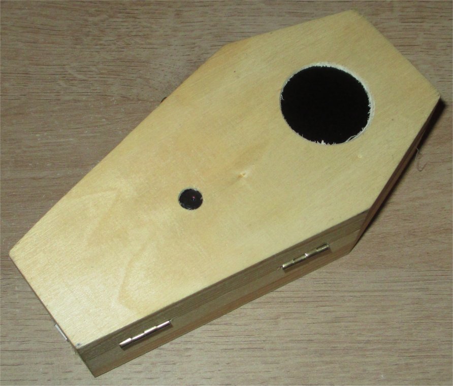
Prelude To The Madness
What better project to resurrect from the incomplete project pile then “The Coffin Tester”? This project was inspired by the chance encounter of a small wooden coffin at a hobby store. With a coffin comes the standard project ideas: Someone is trying to get out or someone is inviting you in. Making both projects at once was my decision.
Overview from 6ft Under
The embedded coffin display in the lid shows classic monster portraits, letting you know who is inside. However, the camera in the lid also takes images of the viewer. When it detects a face, it displays the image on the display, letting you know that you are inside now. A Halloween SFX module within the box fires up and horror ensues. The WiFi capable board within makes future upgrades to functionality possible. The horror never ends.
Part Selection
Additional Stuff
| Materials | |
|---|---|
| Jumper Wires Female/Female | Plastic Fork |
| Strip Board | Painter's Tape |
| Header Pins Male | Hot Glue |
| Header Pins Female | Borated Paraffin |
| Electrical Tape | |
| Heat Shrink Tubing | |
Element Preparation
| Elements | ||||
|---|---|---|---|---|
| Halloween SFX Module | ArduCam ESP32S Uno w/ PSRAM | Coffin Top | Coffin Bottom | |
|
|
|
| |
Assemblies
Block Diagram of Project Elements
- Not in image: A Buzzer was added later to Coffin top.
Coffin Top Assembly
| Coffin Top | ||||
|---|---|---|---|---|
 |
 |
 |
 |
 |
Construction
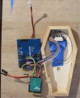
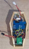
- The main constraint on the build is volume of the Coffin. If only the functions of the ArduCam, Display, SD Card and Buzzer were implemented then space is not an issue. But, addition of additional functions lead to the decision to ensure that all the Coffin Top functions would be implemented within the volume of the Coffin Top.
- The access for power and programming in-place resulted in a USB cable extension capability. This would represent one of the connections between Top and Bottom of Coffin. The inclusion of a Battery charger on the ArduCam meant that a battery could be used to conveniently power the project. This is the second Top/Bottom connection. The SFX Module trigger is the third.
PIN Consideration
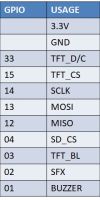
- GPIO 33 - This pin is available on the ArduCam but not on the ESP32Cam which is why the ESP32Cam can be substituted for the ArduCam with the sacrifice of a GPIO Pin and therefore a function. My suggestion would be to sacrifice the Buzzer and reassign Pins.
- GPIO 15, 14, 13 and 12 - This is the standard HSPI Pin assignment on an ESP32. For the ArduCam and ESP32Cam, the onboard SD MMC uses these pins for accessing the SD Card in MMC mode, as well as GPIO 02 and 04. The need for a TFT Display SPI connection is why it is disabled. A SD Card in SPI mode can then be reintegrated into the design.
- GPIO 04 and 02 - These Pins are freed up by disabling SD MMC and are available for project use. See Project Surprises Section for GPIO 02 surprise.
- GPIO 03 and 01 - These are the RX and TX pins. Use of these Pins later in the project can not Pull-Down the Pins as it would interfere with Boot-Up. During software debugging, the RX can be used if serial input is not needed and serial.print can be used to debug and monitor activity. When all the debugging is done, do not use any serial interaction with the monitor and the TX pin is available. However, upon startup/boot the device automatically sends out messages via the TX. So be prepared for the signals on the TX/GPIO 01 Pin. For my implementation, I assigned the buzzer function therefore the project buzzes upon start up.
Coffin Bottom Assembly
Construction
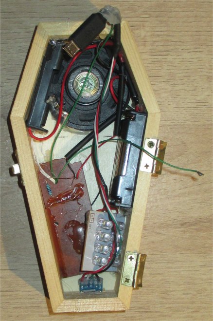
- Well, my decision to document was before my decision to pack it in and glue it down. The primary issues here are space and interface with the Coffin Top circuitry.
- The arrangement of contents needs to accommodate the inclusion of a ICR18650 battery. The battery is a late idea for the project and has not been vetted for safety. So, don't do it. Think of the horror of the device bursting in an explosion of fire and chemicals. Don't!!!
Interconnection Assemblies
| Interconnectors | |
|---|---|
| Part | Design |
 |
 |
 |
 |
Construction
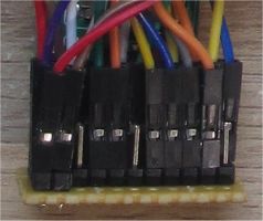
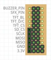
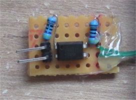
- The Coffin Wired Interface can be abandon for permanent wire soldering and save space. But this was a build and experiment. The jumper wires allows for testing and Pin re-assignment.
- The Optocoupler is routine for isolating devices with different voltages, current issues, power supplies and signal interference.
Assembled
The most time consuming element of the project was packing the coffin. The parts easily fit but all the wiring gets in the way.
- Not in photo: A Buzzer was added later to Coffin top.
Project Surprises:
- GPIO02 boot-up tests for the PSRAM voltage requirement and interfered with startup. Required eFuse setting to permanent PSRAM voltage level for normal operation
- ESP32 Cam with AI-Thinker hardware setup can be used for the project with a simple pin assignment change and the creators choice of one function loss.
- An overly elaborate method for using a vibrating motor to trigger SFX module, isolating the module electrically from Microcontroller abandon due to unnecessary complexity and stray triggering from handling project.
- SFX module uses High Brightness LEDs that cause short bursts of high current that have to be handled by separate battery pack in order to not require additional power supply circuitry for a common power supply.
- I had a ICR18650 lying around, so battery operation of project utilizing built in charging of the ArduCam. Then again, it could be a self-destruct method.
- Had to pin down ArduCam board in coffin, so I used a piece of a plastic fork.
Programming Elements
- TFT display for the ArduCam
- HSPI usage
- Facial Detection Code
- Simple RAW Image decoding for saved images
- Camera image buffer display to TFT display
Demonstration Video
Resource
| Parts | |
|---|---|
| Item | Link |
| ArduCam Product Page | https://www.arducam.com/product/b0192-arducam-iotai-esp32-uno-psram-ov2640-camera/ |
| GCA901A Demo on ESP32 | https://github.com/talofer99/ESP32CAM-Capture-and-send-image-over-esp-now |
| ESP32 SPI Information | https://randomnerdtutorials.com/esp32-spi-communication-arduino/ |
| ESP32 Now | https://randomnerdtutorials.com/esp-now-two-way-communication-esp32/ |
| ESP32 Cam Photo Webserver | https://randomnerdtutorials.com/esp32-cam-take-photo-display-web-server/ |
| ESP32 Cam Selfie | https://robotzero.one/esp32-cam-tft-selfie/ |
| ESP32 Cam Pinout Guide | https://randomnerdtutorials.com/esp32-cam-ai-thinker-pinout/ |
| ESP32 Cam Settings Guide | https://randomnerdtutorials.com/esp32-cam-ov2640-camera-settings/ |
| ESP32 Cam as Camera with Display | https://www.instructables.com/ESP32-ESP32-CAM-With-OV2640-Using-SIPHSPI-for-TFT-/ |
| ESP32 Camera and Webserver Sample Program from hardware library | Ardunio IDE Library |
| ESP-DL | https://github.com/espressif/esp-dl |
Notes
- Seldom does a single link hold all the information needed for a project.
- These represent the different paths taken while researching the basic ESP32, Display integration and face detection.
Code
- The code is a splicing of several programs and samples. See the Resource Section.
- The post_Error function is a placeholder for an expected ESP_NOW functionality and is to serve for simple message broadcast.
Includes
 #include <SPI.h>
 #include "FS.h"
 #include <SD.h>
 #include "Adafruit_GFX.h"
 #include "Adafruit_GC9A01A.h"
 #include "esp_camera.h"
 #include "esp_timer.h"
 #include "human_face_detect_msr01.hpp"
 #include "human_face_detect_mnp01.hpp"
Defines
 // Pin definition for CAMERA_MODEL_AI_THINKER
 #define PWDN_GPIO_NUM     32
 #define RESET_GPIO_NUM    -1
 #define XCLK_GPIO_NUM      0
 #define SIOD_GPIO_NUM     26
 #define SIOC_GPIO_NUM     27

 #define Y9_GPIO_NUM       35
 #define Y8_GPIO_NUM       34
 #define Y7_GPIO_NUM       39
 #define Y6_GPIO_NUM       36
 #define Y5_GPIO_NUM       21
 #define Y4_GPIO_NUM       19
 #define Y3_GPIO_NUM       18
 #define Y2_GPIO_NUM        5
 #define VSYNC_GPIO_NUM    25
 #define HREF_GPIO_NUM     23
 #define PCLK_GPIO_NUM     22

 #define SPI_MOSI 13
 #define SPI_MISO 12
 #define SPI_CLK 14
 #define SPI_SS 15

 #define TFT_DC   33 // Data Command control pin
 #define TFT_CS  15 // Chip select control pin
 #define TFT_RST -1
 #define TFT_BL 3

 #define SD_CS 4
 #define SFX_MODULE_PIN 2
 #define BUZZER_PIN 1

 #define TFT_ROTATION 0 // 0 to 3
Initializations
 SPIClass MySPI(HSPI); // Declare an HSPI bus object (to use or BOTH TFT and SD-card)
 Adafruit_GC9A01A tft(&MySPI, TFT_DC, TFT_CS);
 boolean camera_ok;

 boolean InitSD()
 {
   boolean success=SD.begin(SD_CS,MySPI);
   if (!success)
     {
        post_Error("Fail: check formatted SD-card is in!");
        return false;
     }

   listDir(SD, "/", 0);
   return success;
 }

 boolean camera_init()
 {
   camera_config_t config;
   config.ledc_channel = LEDC_CHANNEL_0;
   config.ledc_timer = LEDC_TIMER_0;
   config.pin_d0 = Y2_GPIO_NUM;
   config.pin_d1 = Y3_GPIO_NUM;
   config.pin_d2 = Y4_GPIO_NUM;
   config.pin_d3 = Y5_GPIO_NUM;
   config.pin_d4 = Y6_GPIO_NUM;
   config.pin_d5 = Y7_GPIO_NUM;
   config.pin_d6 = Y8_GPIO_NUM;
   config.pin_d7 = Y9_GPIO_NUM;
   config.pin_xclk = XCLK_GPIO_NUM;
   config.pin_pclk = PCLK_GPIO_NUM;
   config.pin_vsync = VSYNC_GPIO_NUM;
   config.pin_href = HREF_GPIO_NUM;
   config.pin_sscb_sda = SIOD_GPIO_NUM;
   config.pin_sscb_scl = SIOC_GPIO_NUM;
   config.pin_pwdn = PWDN_GPIO_NUM;
   config.pin_reset = RESET_GPIO_NUM;
   config.xclk_freq_hz = 20000000;
   config.pixel_format = PIXFORMAT_RGB565;
   if (psramFound())
     { // larger bufer
       config.frame_size = FRAMESIZE_QVGA;
       config.jpeg_quality = 2;
       config.fb_count = 2;
       config.grab_mode = CAMERA_GRAB_LATEST;
     }
    else
     { // smaller buffer
       config.frame_size = FRAMESIZE_QVGA;
       config.jpeg_quality = 12;
       config.fb_count = 1;
     }

   esp_err_t err = esp_camera_init(&config);
   if (err != ESP_OK)
     {
       post_Error("Camera init failed with error: "+String(err));
       return false;;
     }

   sensor_t * s = esp_camera_sensor_get();
   s->set_hmirror(s, 1);        // 0 = disable , 1 = enable
   s->set_vflip(s, 1);          // 0 = disable , 1 = enable
   return true;
 }
Core
 void setup()
 {
    delay(200);
    pinMode(BUZZER_PIN,OUTPUT);
    pinMode(TFT_CS,OUTPUT);
    pinMode(SD_CS,OUTPUT);
    pinMode(SFX_MODULE_PIN,OUTPUT);

    analogWrite(TFT_BL,255);

    tft.begin();
    tft.setRotation(TFT_ROTATION);
    tft.setTextColor(GC9A01A_WHITE);
    tft.setTextSize(2);
    tft_clear();
    tft.println("Hello World");

    InitSD();
    camera_ok=camera_init();
    if (!camera_ok) post_Error("but without Camera");
    delay(1000);
   randomSeed(analogRead(0));
 }

 void loop()
 {
   int face_test = 0;
   int loop_count = 25;

   tft_clear();
   TFT_fade(-1,10);
   display_randon_sd_raw();
   TFT_fade(1,10);
   for(int x = 0; x < loop_count; ++x)
     {
       if (xcapture_handler(&face_test) == 100)
         {
           buzzer_zap(200);
           SFX_Module_Fire();
           delay(5000);
           x = loop_count;
         }
     }
 }
Display Functions
 void tft_clear()
 {
   tft.fillScreen(GC9A01A_BLACK);
   tft.setCursor(0,0); // top
 }

 void TFT_fade(int fade_type, int fade_delay)
 {
   switch (fade_type)
     {
       case 1:
         for(int x=0;x<256;++x)
           {
             analogWrite(TFT_BL,x);
             delay(fade_delay);
           }
         break;
       case -1:
         for(int x=255;x>-1;--x)
           {
             analogWrite(TFT_BL,x);
             delay(fade_delay);
           }
         analogWrite(TFT_BL,0);
         analogWrite(TFT_BL,0);
         analogWrite(TFT_BL,0);
         break;
     }
   delay(fade_delay);
 }
Stored Image Functions
 String picture_gallery[64];
 int picture_gallery_size = 0;
 void listDir(fs::FS &fs, const char * dirname, uint8_t levels)
 {

   File root = fs.open(dirname);
   if (!root)
     {
       post_Error("Failed to open directory");
       return;
     }
   if (!root.isDirectory())
     {
       post_Error("Not a directory");
       return;
     }

   File file = root.openNextFile();
   while(file)
     {
       if (file.isDirectory())
         {
           if (levels)
             {
               listDir(fs, file.name(), levels -1);
             }
         }
        else
         {
           picture_gallery[picture_gallery_size] = file.name();
           ++picture_gallery_size;
         }
       file = root.openNextFile();
     }
 }

 void display_randon_sd_raw()
 {
   int choice = random(picture_gallery_size);
   int success;

   success = sd_load_and_display_raw("/"+picture_gallery[choice]);
 }
Displaying Images
 int generate_image_from_camera(camera_fb_t *fb)
 {
   uint16_t *data = (uint16_t *)fb->buf;
   uint16_t pixel_data;

   for(uint16_t y=0;y<240;++y)
     {
       data = data + 40;
       for(uint16_t x=0;x<240;++x)
         {
           pixel_data = *data;
           pixel_data = (((pixel_data) & 0xFF00) >> 8) | (((pixel_data) & 0xFF) << 8);
           tft.drawRGBBitmap(x,y, &pixel_data,1,1);
           ++data;
         }
       data = data + 40;
     }
   return(1);
 }

 int sd_load_and_display_raw(String file_name)
 {
   char pixel_red;
   char pixel_green;
   char pixel_blue;
   uint16_t pixel_data;
   uint16_t pixel_datar;
   uint16_t pixel_datag;
   uint16_t pixel_datab;
   uint8_t test_line[724];

   File file_pointer = SD.open(file_name);
   if (!file_pointer)
     post_Error("File not found: "+file_name);

   file_pointer.read(test_line,54);

   for(int y=0;y<240;++y)
     {
       file_pointer.read(test_line,720);
       for(int x=0;x<240;++x)
         {
           pixel_red = test_line[(x*3)];
           pixel_green = test_line[(x*3)+1];
           pixel_blue = test_line[(x*3)+2];

           pixel_datar = pixel_red;
           pixel_datar = pixel_datar & 0b0000000011111000;
           pixel_datar = pixel_datar << 8;
           pixel_datag = ((pixel_green & 0b11100000) >> 2) | pixel_red & 0b00000111;;
           pixel_datag = pixel_datag << 5;
           pixel_datab = (pixel_blue & 0b11111000) >> 3;
           pixel_data = pixel_datar | pixel_datag | pixel_datab;
           tft.drawRGBBitmap(x,y, &pixel_data,1,1);
         }
     }

   if (file_pointer)
     file_pointer.close();

   return(1);
 }
Remains
 void post_Error(String message)
 {
 //  Place Holder
 //
 }

 #define SFX_TRIGGER_LENGTH 25
 void SFX_Module_Fire()
 {
   digitalWrite(SFX_MODULE_PIN,HIGH);
   delay(SFX_TRIGGER_LENGTH);
   digitalWrite(SFX_MODULE_PIN,LOW);
 }

 void buzzer_zap(int buzz_time)
 {
   digitalWrite(BUZZER_PIN,HIGH);
   delay(buzz_time);
   digitalWrite(BUZZER_PIN,LOW);
 }

 static esp_err_t xcapture_handler(int *req)
 {
   camera_fb_t *fb = NULL, *temp_fb;
   esp_err_t res = ESP_OK;
   int64_t fr_start = esp_timer_get_time();
   res = 0;

   fb = esp_camera_fb_get();

   if (!fb)
     {
       return ESP_FAIL;
     }

   bool detected = false;
   int face_id = 0;

   // Code Snipet from Webserver ESP32-Cam demonstration example code
   // Hard to balance in this application
   // Higher Reliability Testing
   //  HumanFaceDetectMSR01 s1(0.01F, 0.5F, 10, 0.2F);
   //  HumanFaceDetectMNP01 s2(0.5F, 0.3F, 5);
   //  std::list<dl::detect::result_t> &candidates = s1.infer((uint16_t *)fb->buf, {(int)fb->height, (int)fb->width, 3});
   //  std::list<dl::detect::result_t> &results = s2.infer((uint16_t *)fb->buf, {(int)fb->height, (int)fb->width, 3}, candidates);

    // Lower Reliability Testing
   HumanFaceDetectMSR01 s1(0.1F, 0.5F, 10, 0.4F);
   std::list<dl::detect::result_t> &results = s1.infer((uint16_t *)fb->buf, {(int)fb->height, (int)fb->width, 3});

   if (results.size() > 0)
     {
       generate_image_from_camera(fb);
       delay(1000) ;
       res = 100;
     }
   esp_camera_fb_return(fb);

   int64_t fr_end = esp_timer_get_time();
   int64_t fr_delta = fr_end - fr_start;

   return res;
 }
