Group Project ELEPHANT 1.0: Difference between revisions
Jump to navigation
Jump to search
No edit summary |
No edit summary |
||
| (24 intermediate revisions by one other user not shown) | |||
| Line 1: | Line 1: | ||
[[File:GP_LVL1_ELEPHANT_PORTRAIT_1_1.jpg]] | |||
== Information == | |||
[[File: | [[File:GP_LVL1_ELEPHANT_1_0_WWW.JPG]] | ||
== Structure Parts List == | |||
Table Leg | |||
Wooden Bowl | |||
Broken Wooden Bowl | |||
2 U-Bolts and nuts | |||
Wooden Panel Board Scrap | |||
Chain | |||
== Parts List == | == Electronics Parts List == | ||
Raspberry PI B | Raspberry PI B | ||
| Line 36: | Line 49: | ||
1 Dual 10K Potentiometer (logarithmic) | 1 Dual 10K Potentiometer (logarithmic) | ||
= | == Electronics Build == | ||
[[File: | [[File:GP_LVL1_ELEPHANT_1_1_PINOUT.JPG]] | ||
'''NOTE:''' GPIO conflict between GPIO18 and audio resulted in NEOPIXEL GPIO pin change from GPIO18 to GPIO10. This change is not reflected in all illustrations and photos. | |||
[[File: | [[File:GP_LVL1_ELEPHANT_1_1_WIRING.JPG]] | ||
'''NOTE:''' NEOPIXEL GPIO changed from 18 to 10. Previous wire X'ed out in RED. | |||
[[File:GP_LVL1_ELEPHANT_1_0_PANEL_LAYOUT.JPG]] | |||
== Actual Photos == | |||
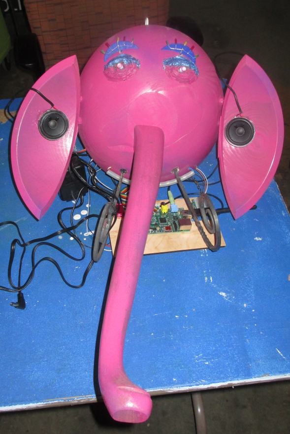
=== Front of Assembly === | |||
[[File:GP_LVL1_ELEPHANT_PORTRAIT_1_1.jpg]] | |||
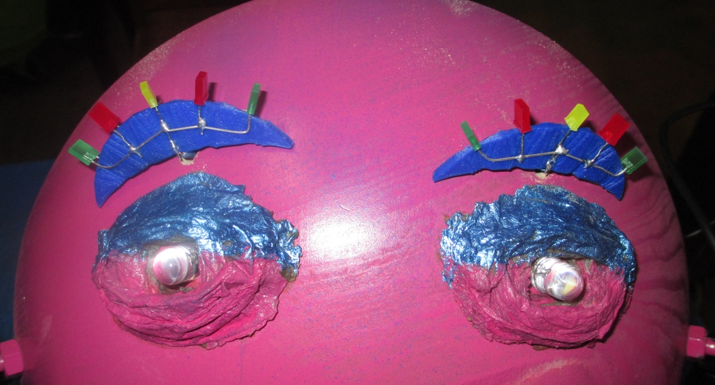
=== Eyes and Brow Close Up === | |||
[[File:GP_LVL1_ELEPHANT_EYES_BROWS_1_1.jpg]] | |||
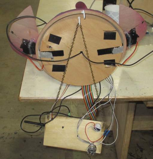
=== Rear of Assembly === | |||
[[File:GP_LVL1_ELEPHANT_HEAD_BACK_2.jpg]] | |||
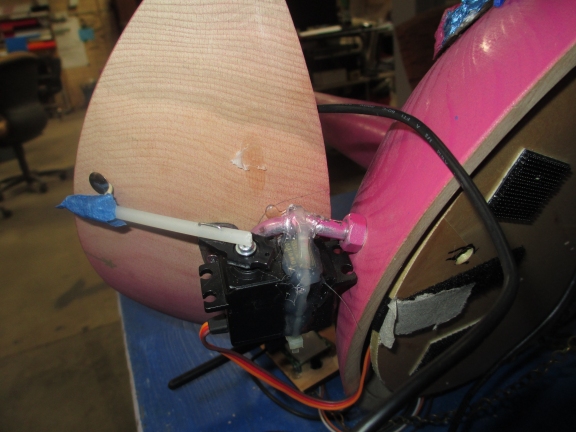
=== Ear and Servo Linkage === | |||
[[File:GP_LVL1_ELEPHANT_HEAD_BACK_EAR_LINKAGE_1_1.jpg]] | |||
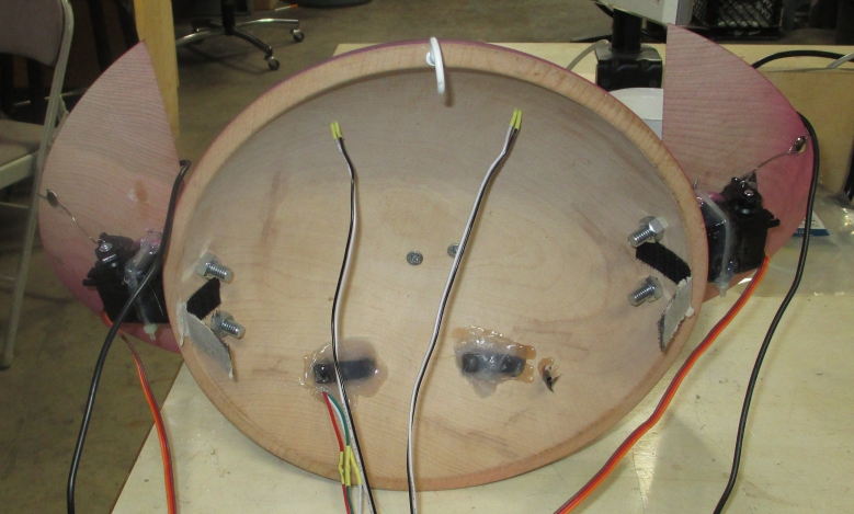
=== Inside of Head === | |||
[[File:GP_LVL1_ELEPHANT_HEAD_BACK_1.jpg]] | |||
'''Note:''' Picture prior to eye brow installation. | |||
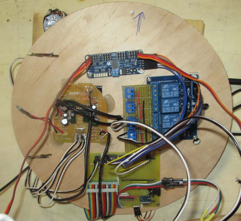
=== Electronics in Head === | |||
[[File:GP_LVL1_ELEPHANT_ELECTRONICS_1.jpg]] | |||
=== Control Panel === | |||
[[File:GP_LVL1_ELEPHANT_CONTROL_PANEL_1.jpg]] | |||
== Source Code == | |||
https://github.com/polewskm/lvl1-elephant | |||
Latest revision as of 21:01, 10 January 2020
Information
Structure Parts List
Table Leg
Wooden Bowl
Broken Wooden Bowl
2 U-Bolts and nuts
Wooden Panel Board Scrap
Chain
Electronics Parts List
Raspberry PI B
4 Relay Module
NeoPixel Strip
PIR Motion Sensor
PCA9685 Adafruit's 16-channel 12-bit PWM/Servo Driver
5.5 mm Barrel Jack
4 LEDs
SPST Switch
100 Ohm Resistor 1W
150 Ohm Resistor 1W
1k Ohms Resistor 1/4 W
10K Resistor 1/4 W
1 Pair USB Powered Speakers
1 Dual 10K Potentiometer (logarithmic)
Electronics Build
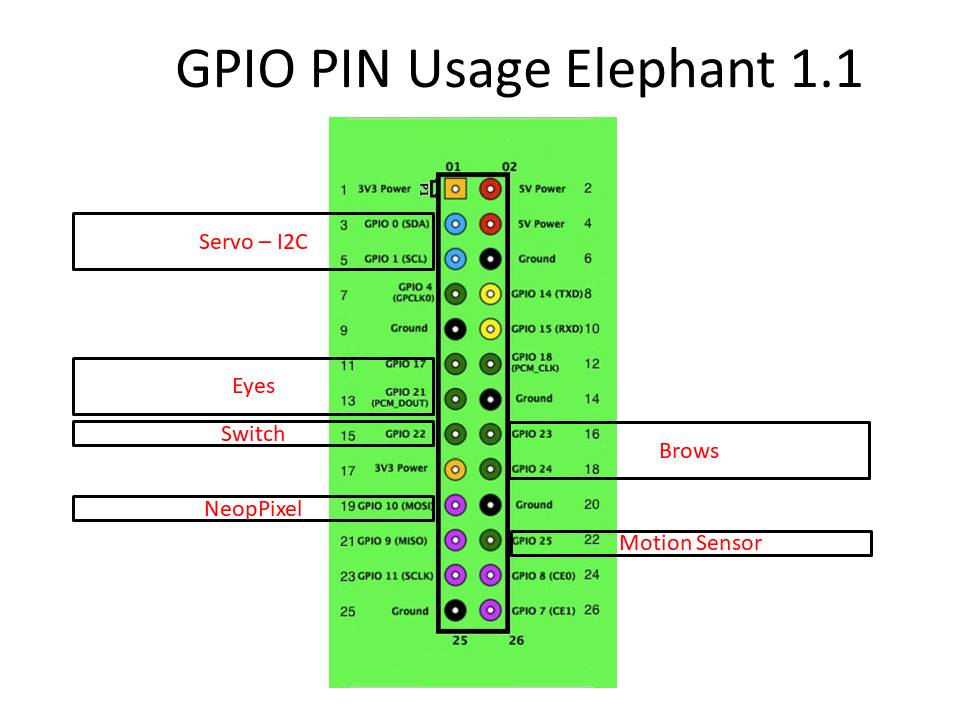
NOTE: GPIO conflict between GPIO18 and audio resulted in NEOPIXEL GPIO pin change from GPIO18 to GPIO10. This change is not reflected in all illustrations and photos.
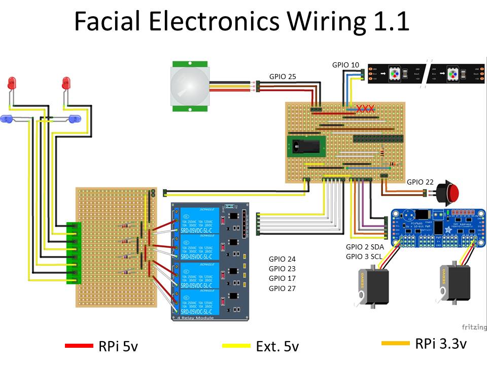
NOTE: NEOPIXEL GPIO changed from 18 to 10. Previous wire X'ed out in RED.
Actual Photos
Front of Assembly
Eyes and Brow Close Up
Rear of Assembly
Ear and Servo Linkage
Inside of Head
Note: Picture prior to eye brow installation.
Electronics in Head
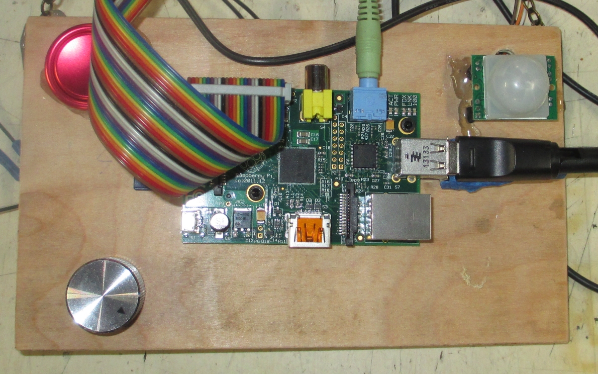
Control Panel
