2nd Inning: Difference between revisions
Jump to navigation
Jump to search
Notyou007a (talk | contribs) No edit summary |
|||
| (4 intermediate revisions by one other user not shown) | |||
| Line 1: | Line 1: | ||
__NOTOC__ | |||
==Introduction== | ==Introduction== | ||
'''Blinking LED''' | '''Blinking LED''' | ||
| Line 9: | Line 10: | ||
*Solderless Breadboard | *Solderless Breadboard | ||
*Hookup wire 22gauge solid | *Hookup wire 22gauge solid | ||
*LED | |||
*1Kohm resistor - that is a 1000 ohm resistor brown-black-red | |||
==How to== | ==How to== | ||
# cut and strip wire as needed. | |||
# put the components on the breadboard | |||
# wire like the Fritzing example | |||
# cut and paste the code | |||
# run and watch the blink | |||
# adjust the delays ie delay(1000) in the code and re-run. The 1000 mean 1000 milliseconds or 1 second | |||
# If the LED does not work, turn it around! | |||
==Schematic== | ==Schematic== | ||
| Line 66: | Line 76: | ||
==Troubleshooting== | ==Troubleshooting== | ||
*If the LED does not work, turn it around! | |||
*plug the side of the resistor that goes to pin 13 directly into the 5V bus to see if the led lights. | |||
[[Category:HOWTO]] | |||
Latest revision as of 23:49, 25 June 2015
Introduction
Blinking LED
Components Needed
- Freeduino or Arduino or clone
- USB cable for Freeduino
- Freeduino development software - download here!
- Solderless Breadboard
- Hookup wire 22gauge solid
- LED
- 1Kohm resistor - that is a 1000 ohm resistor brown-black-red
How to
- cut and strip wire as needed.
- put the components on the breadboard
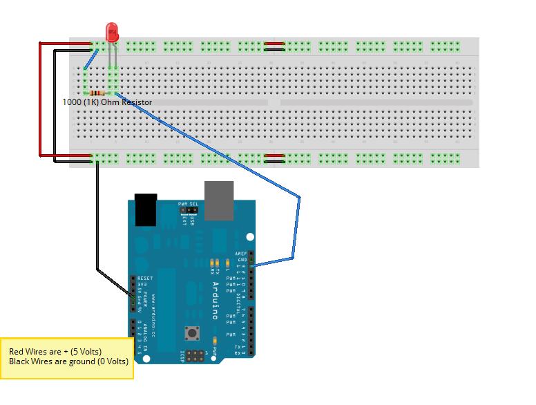
- wire like the Fritzing example
- cut and paste the code
- run and watch the blink
- adjust the delays ie delay(1000) in the code and re-run. The 1000 mean 1000 milliseconds or 1 second
- If the LED does not work, turn it around!
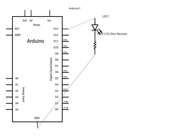
Schematic
Fritzing
Code
/*
  Blink

 Turns on an LED on for one second, then off for one second, repeatedly.

 The circuit:
 * LED connected from digital pin 13 to ground.

 * Note: On most Arduino boards, there is already an LED on the board
 connected to pin 13, so you don't need any extra components for this example.


 Created 1 June 2005
 By David Cuartielles

 http://arduino.cc/en/Tutorial/Blink

 based on an orginal by H. Barragan for the Wiring i/o board

 */

int ledPin =  13;    // LED connected to digital pin 13

// The setup() method runs once, when the sketch starts

void setup()   {
  // initialize the digital pin as an output:
  pinMode(ledPin, OUTPUT);
}

// the loop() method runs over and over again,
// as long as the Arduino has power

void loop()
{
  digitalWrite(ledPin, HIGH);   // set the LED on
  delay(1000);                  // wait for a second
  digitalWrite(ledPin, LOW);    // set the LED off
  delay(1000);                  // wait for a second
}
Troubleshooting
- If the LED does not work, turn it around!
- plug the side of the resistor that goes to pin 13 directly into the 5V bus to see if the led lights.

