Difference between revisions of "6th Inning"
Jump to navigation
Jump to search
(→How to) |
|||
| Line 14: | Line 14: | ||
==How to== | ==How to== | ||
| − | + | #Connect the two outer wires to the power bus (5v) and Ground (0v) | |
| + | #Connect the middle wire to Analog 0 | ||
==Schematic== | ==Schematic== | ||
Revision as of 22:50, 17 May 2010
Contents
Introduction
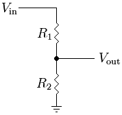
Potentiometers and voltage dividers This inning we will hook up a potentiometer and play with voltage dividers. A voltage divider is a simple circuit where you have two resistors in series and you are reading the voltage in between the two resistors. These are very important because there are many sensors that are resistive in nature, so all you have to do is put the sensor in series with a resistor and read the changing value on an analog pin! Check out the wikipedia article...http://en.wikipedia.org/wiki/Voltage_divider
Components Needed
- Freeduino or Arduino or clone
- USB cable for Freeduino
- Freeduino development software - download here!
- Solderless Breadboard
- Hookup wire 22gauge solid
- potentiometer soldered up to a couple of long leads
How to
- Connect the two outer wires to the power bus (5v) and Ground (0v)
- Connect the middle wire to Analog 0
