Difference between revisions of "3rd Inning"
Jump to navigation
Jump to search
(→Code) |
|||
| Line 24: | Line 24: | ||
==Code== | ==Code== | ||
| + | <pre> | ||
| + | int RED = 9; // RED pin of the LED to PWM pin 0 | ||
| + | int GREEN = 10; // GREEN pin of the LED to PWM pin 1 | ||
| + | int BLUE = 11; // BLUE pin of the LED to PWM pin 2 | ||
| + | |||
| + | void setup() | ||
| + | { | ||
| + | // nothing for setup | ||
| + | } | ||
| + | |||
| + | void loop() | ||
| + | { | ||
| + | for(int r = 0; r < 1024; r+=5) { | ||
| + | for(int g = 0; g < 1024; g+=5) { | ||
| + | for(int b = 0; b < 1024; b+=5) { | ||
| + | analogWrite(RED, r); | ||
| + | analogWrite(GREEN, g); | ||
| + | analogWrite(BLUE, b); | ||
| + | delay(30); | ||
| + | } | ||
| + | } | ||
| + | } | ||
| + | } | ||
| + | |||
| + | |||
| + | |||
| + | |||
| + | </pre> | ||
==Troubleshooting== | ==Troubleshooting== | ||
Revision as of 19:27, 16 May 2010
Contents
Introduction
Tri-color LED fading
Components Needed
- Freeduino or Arduino or clone
- USB cable for Freeduino
- Freeduino development software - download here!
- Solderless Breadboard
- Hookup wire 22gauge solid
- Common Cathode LED
How to
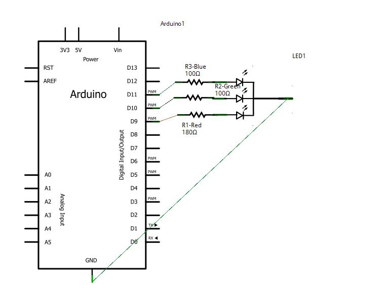
- refer to the fritzing drawing to place the wires
- upload the code below using cut and paste
- Run and watch the fading of the led!
Schematic
Fritzing
Code
int RED = 9;    // RED pin of the LED to PWM pin 0
int GREEN = 10;  // GREEN pin of the LED to PWM pin 1
int BLUE = 11;   // BLUE pin of the LED to PWM pin 2

void setup()
{
  // nothing for setup
}

void loop()
{
  for(int r = 0; r < 1024; r+=5) {
    for(int g = 0; g < 1024; g+=5) {
      for(int b = 0; b < 1024; b+=5) {
        analogWrite(RED, r);
        analogWrite(GREEN, g);
        analogWrite(BLUE, b);
        delay(30);
      }
    }
  }
}
Troubleshooting
- is your led in correctly
- code for the pins on Arduino correct
Resources
Most of this example was taken from here.

