Difference between revisions of "Diorama Castle"
Jump to navigation
Jump to search
| Line 2: | Line 2: | ||
==== LVL1 Sign ==== | ==== LVL1 Sign ==== | ||
| − | |||
| − | |||
| − | |||
| − | |||
| − | |||
{| border="1" | {| border="1" | ||
| Line 26: | Line 21: | ||
|[[File:Flash_Circuit_Bottom.jpg]] | |[[File:Flash_Circuit_Bottom.jpg]] | ||
|- | |- | ||
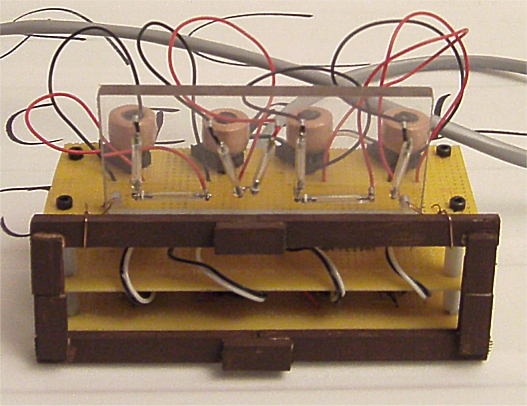
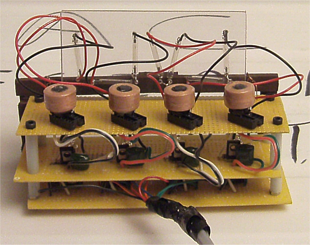
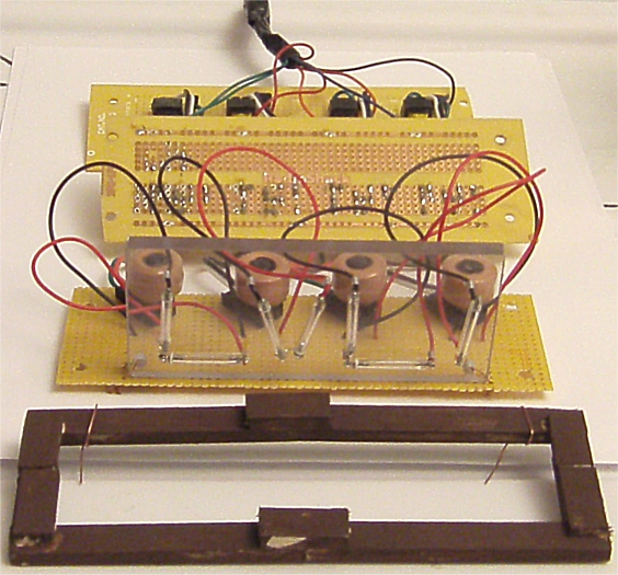
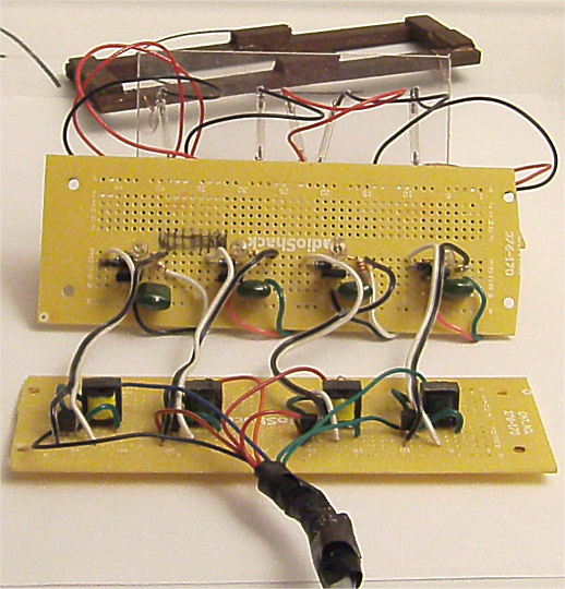
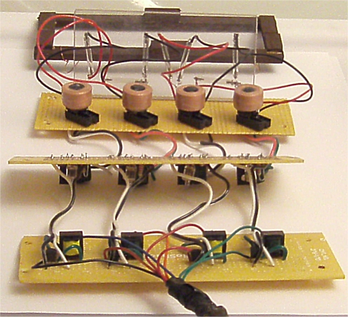
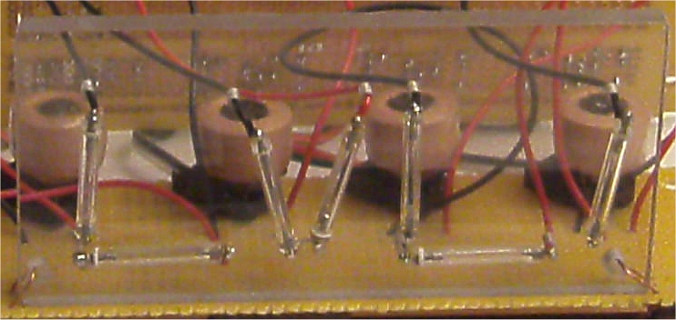
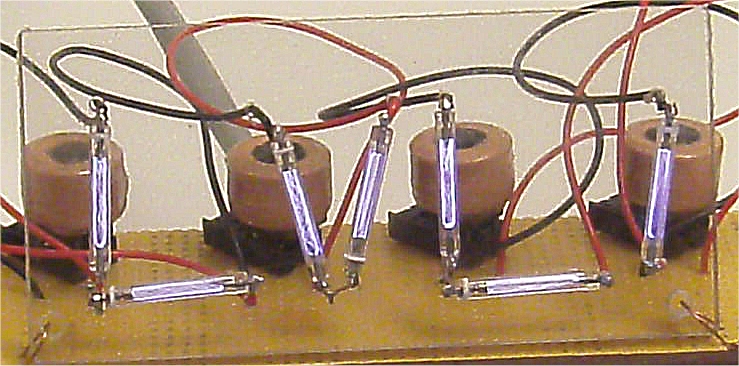
| − | |The construction of the sign is in three parts. The sign has a simple stained wood fascade. The actual sign portion is a lexan rectangle with xenon flash tubes arranged and wired inplace to form "LVL1". The main body consists of three layers of circuit boards. The bottom layer has the high voltage charging circuit made from the camera parts. The middle level has the charging capacitor and SCR trigger circuit. The top layer has the trigger coils plugged into IC sockets. The trigger coils do short-out, so they are in sockets for easy replacement. | + | |The construction of the sign is in three parts. The sign has a simple stained wood fascade. The actual sign portion is a lexan rectangle with xenon flash tubes arranged and wired inplace to form "LVL1". The main body consists of three layers of circuit boards. The bottom layer has the high voltage charging circuit made from the camera parts. The middle level has the charging capacitor and SCR trigger circuit. The top layer has the trigger coils plugged into IC sockets. The trigger coils do short-out, so they are in sockets for easy replacement. |
| + | |- | ||
| + | |[[File:LVL1-Assembled-Back.jpg]] | ||
|- | |- | ||
|[[File:LVL1-Unassembled-1a.jpg]] | |[[File:LVL1-Unassembled-1a.jpg]] | ||
| Line 40: | Line 37: | ||
|[[File:LVL1-Switch-Box.jpg]] | |[[File:LVL1-Switch-Box.jpg]] | ||
|- | |- | ||
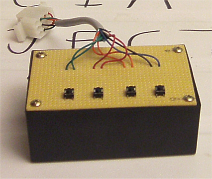
| − | | | + | |Finally, the sign is powered by 4 AA batteries in a switch box. Each letter in the sign has a seperate switch. |
|} | |} | ||

