Difference between revisions of "Diorama Castle"
| Line 4: | Line 4: | ||
The LVL1 sign is a collection of four duplicate circuits. Each circuit provides a high voltage charge to a xenon flash tube. The voltage is not discharged such that the tube flashes, but instead allows streaks of plasma to form between the two ends. The circuits are divided into two parts. The first part is the charging circuit from disposal cameras with a flash. The internal flash module is scavenged for its transistor, step-up transformer, resistor and diode. The components are wired as before on a perfboard. The second ciruit is based on a strobe light. The trigger ciruit charges a capacitor. When charged, the capacitor allows current to light the neon lamp which triggers the SCR. The triggered SCR, shorts out the capacitor through the trigger coil with the output end and ground attached to the flash tube. The camera circuit does provide a capacitor and trigger coil, but they are not capable of making the plasma streaks as bright as the substituted components. | The LVL1 sign is a collection of four duplicate circuits. Each circuit provides a high voltage charge to a xenon flash tube. The voltage is not discharged such that the tube flashes, but instead allows streaks of plasma to form between the two ends. The circuits are divided into two parts. The first part is the charging circuit from disposal cameras with a flash. The internal flash module is scavenged for its transistor, step-up transformer, resistor and diode. The components are wired as before on a perfboard. The second ciruit is based on a strobe light. The trigger ciruit charges a capacitor. When charged, the capacitor allows current to light the neon lamp which triggers the SCR. The triggered SCR, shorts out the capacitor through the trigger coil with the output end and ground attached to the flash tube. The camera circuit does provide a capacitor and trigger coil, but they are not capable of making the plasma streaks as bright as the substituted components. | ||
| + | |||
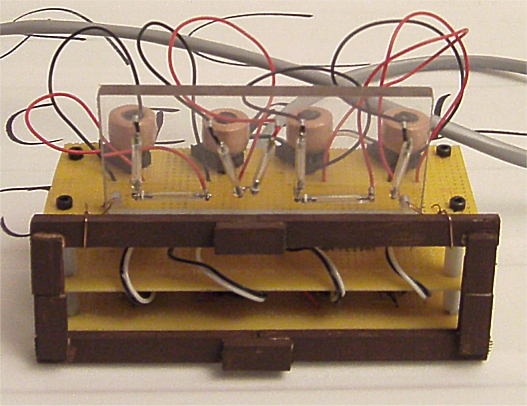
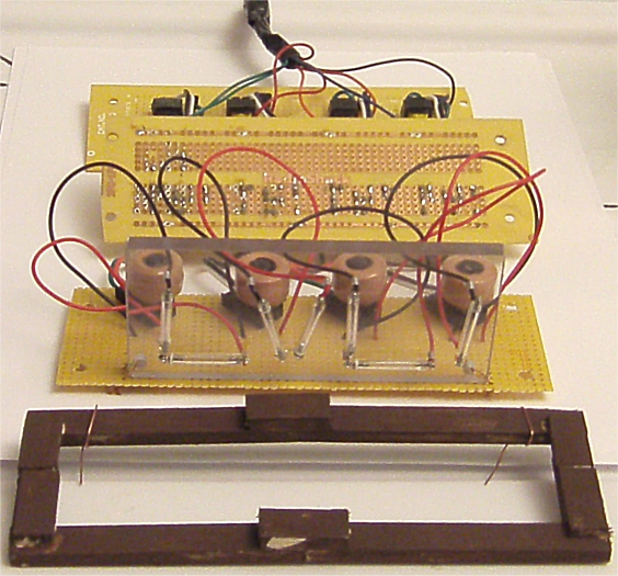
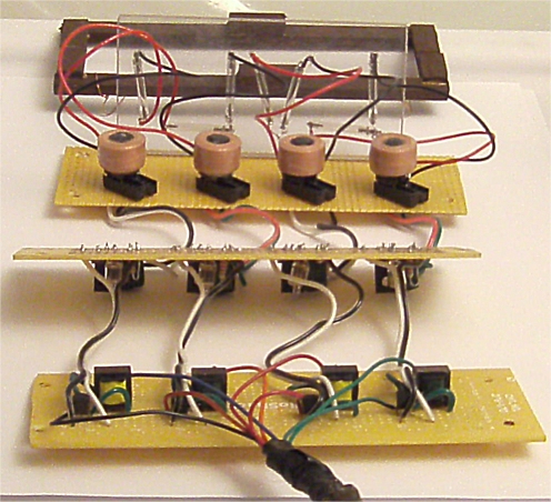
| + | The construction of the sign is in three parts. The sign has a simple stained wood fascade. The actual sign portion is a lexan rectangle with xenon flash tubes arranged and wired inplace to form "LVL1". The main body consists of three layers of circuit boards. The bottom layer has the high voltage charging circuit made from the camera parts. The middle level has the charging capacitor and SCR trigger circuit. The top layer has the trigger coils plugged into IC sockets. The trigger coils do short-out, so they are in sockets for easy replacement. | ||
{| border="1" | {| border="1" | ||
| + | |- | ||
| + | |[[File:LVL1-Assembled-On.jpg]] | ||
| + | |- | ||
| + | |The LVL1 sign is a collection of four duplicate circuits. Each circuit provides a high voltage charge to a xenon flash tube. The voltage is not discharged such that the tube flashes, but instead allows streaks of plasma to form between the two ends. | ||
|- | |- | ||
|[[File:LVL1-Assembled-Off.jpg]] | |[[File:LVL1-Assembled-Off.jpg]] | ||
| − | |||
| − | |||
|- | |- | ||
|[[File:Plasma_Tube_Schematic.jpg]] | |[[File:Plasma_Tube_Schematic.jpg]] | ||
|- | |- | ||
|[[File:Plasma_Tube_Parts.jpg]] | |[[File:Plasma_Tube_Parts.jpg]] | ||
| + | |- | ||
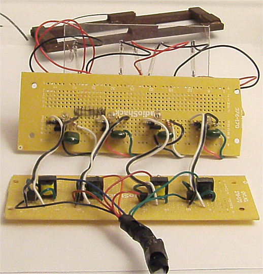
| + | |The circuits are divided into two parts. The first part is the charging circuit from disposal cameras with a flash. The internal flash module is scavenged for its transistor, step-up transformer, resistor and diode. The components are wired as before on a perfboard. The second ciruit is based on a strobe light. The trigger ciruit charges a capacitor. When charged, the capacitor allows current to light the neon lamp which triggers the SCR. The triggered SCR, shorts out the capacitor through the trigger coil with the output end and ground attached to the flash tube. The camera circuit does provide a capacitor and trigger coil, but they are not capable of making the plasma streaks as bright as the substituted components. | ||
|- | |- | ||
|[[File:Flash_Circuit_Top.jpg]] | |[[File:Flash_Circuit_Top.jpg]] | ||
|- | |- | ||
|[[File:Flash_Circuit_Bottom.jpg]] | |[[File:Flash_Circuit_Bottom.jpg]] | ||
| + | |- | ||
| + | |The construction of the sign is in three parts. The sign has a simple stained wood fascade. The actual sign portion is a lexan rectangle with xenon flash tubes arranged and wired inplace to form "LVL1". The main body consists of three layers of circuit boards. The bottom layer has the high voltage charging circuit made from the camera parts. The middle level has the charging capacitor and SCR trigger circuit. The top layer has the trigger coils plugged into IC sockets. The trigger coils do short-out, so they are in sockets for easy replacement. | ||
|- | |- | ||
|[[File:LVL1-Unassembled-1a.jpg]] | |[[File:LVL1-Unassembled-1a.jpg]] | ||
Revision as of 22:05, 19 October 2011
LVL1 Presents
LVL1 Sign
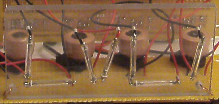
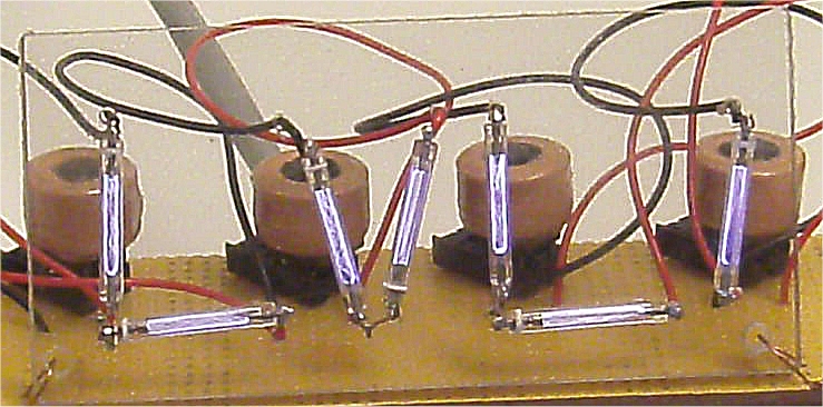
The LVL1 sign is a collection of four duplicate circuits. Each circuit provides a high voltage charge to a xenon flash tube. The voltage is not discharged such that the tube flashes, but instead allows streaks of plasma to form between the two ends. The circuits are divided into two parts. The first part is the charging circuit from disposal cameras with a flash. The internal flash module is scavenged for its transistor, step-up transformer, resistor and diode. The components are wired as before on a perfboard. The second ciruit is based on a strobe light. The trigger ciruit charges a capacitor. When charged, the capacitor allows current to light the neon lamp which triggers the SCR. The triggered SCR, shorts out the capacitor through the trigger coil with the output end and ground attached to the flash tube. The camera circuit does provide a capacitor and trigger coil, but they are not capable of making the plasma streaks as bright as the substituted components.
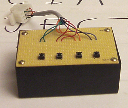
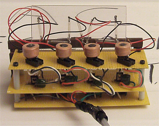
The construction of the sign is in three parts. The sign has a simple stained wood fascade. The actual sign portion is a lexan rectangle with xenon flash tubes arranged and wired inplace to form "LVL1". The main body consists of three layers of circuit boards. The bottom layer has the high voltage charging circuit made from the camera parts. The middle level has the charging capacitor and SCR trigger circuit. The top layer has the trigger coils plugged into IC sockets. The trigger coils do short-out, so they are in sockets for easy replacement.

