Difference between revisions of "Micro-Laser Cutter Project"
Jump to navigation
Jump to search
| Line 3: | Line 3: | ||
== The Mechanism and the rest== | == The Mechanism and the rest== | ||
| − | The mechanical core of the project is the axis movement. | + | *The mechanical core of the project is the axis movement. Movement is driven by stepper motors and threaded rod with a threaded spacer. The spacer has a perfboard piece mounted with guide rail slots called a carrier. The carrier moves along the threaded rod and activates limit switches. |
| − | + | ||
| − | *[[File:MLC-Slide2.JPG]] | + | [[File:MLC-Slide1.JPG]] |
| + | |||
| + | The threadeds rod is mounted in small bearings for smooth movement. One end locks the bearings inplace with two nuts while the other end is press-fit over a rubber tube on the threaded rod end. | ||
| + | The stepper motor and threaded rod are coupled with a threaded spacer, shrink wrap tubing and some crazy glue. | ||
| + | The axle supports are held in place by dual row header pins. | ||
| + | |||
| + | *Although the device only moves in two axes, three drive axis are employed. One stepper motor for X-Axis movement and two for Y-Axis movement. | ||
| + | [[File:MLC-Slide2.JPG]] | ||
*[[File:MLC-Mechanism.jpg]] | *[[File:MLC-Mechanism.jpg]] | ||
*[[File:MLC-Mechanism-Rear.jpg]] | *[[File:MLC-Mechanism-Rear.jpg]] | ||
Revision as of 12:03, 13 September 2011
Out of Spite
When LVL1 was discussing the purchase of a Laser Cutter, one of its members said "I could build one before you get around to buying one." And so the race began. Then on 7/13/2011, the Micro-Laser Cutter was demonstrated. On 7/14/2011, the purchased laser cutter arrived. So, the member built a laser cutter faster than the space could buy one.
The Mechanism and the rest
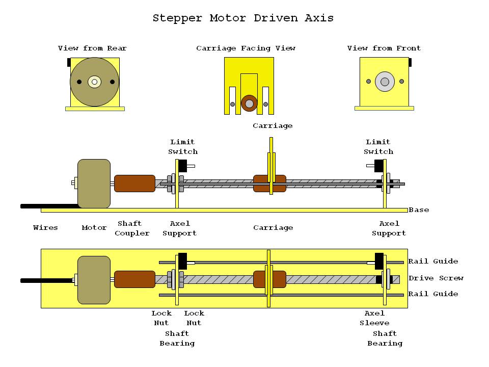
- The mechanical core of the project is the axis movement. Movement is driven by stepper motors and threaded rod with a threaded spacer. The spacer has a perfboard piece mounted with guide rail slots called a carrier. The carrier moves along the threaded rod and activates limit switches.
The threadeds rod is mounted in small bearings for smooth movement. One end locks the bearings inplace with two nuts while the other end is press-fit over a rubber tube on the threaded rod end. The stepper motor and threaded rod are coupled with a threaded spacer, shrink wrap tubing and some crazy glue. The axle supports are held in place by dual row header pins.
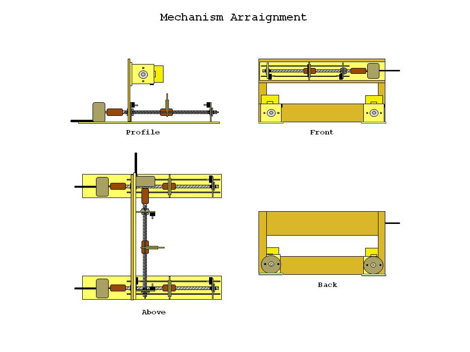
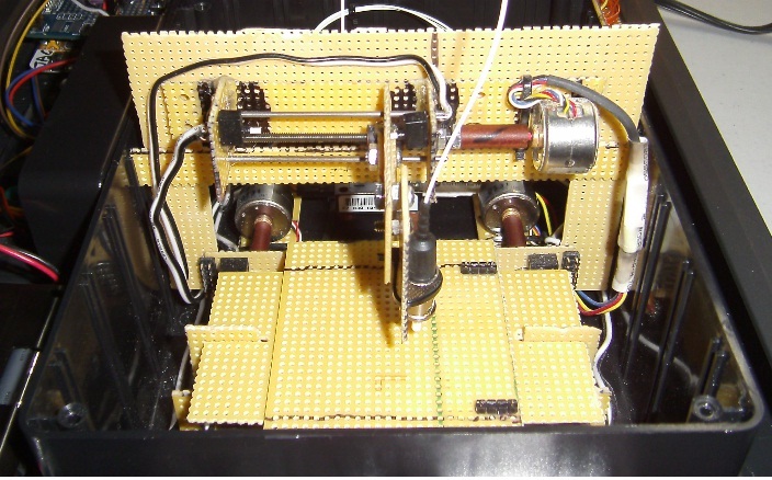
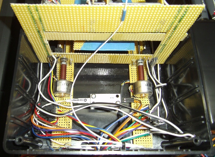
- Although the device only moves in two axes, three drive axis are employed. One stepper motor for X-Axis movement and two for Y-Axis movement.
