Difference between revisions of "Theremin"
Jump to navigation
Jump to search
| Line 12: | Line 12: | ||
* Power Supply | * Power Supply | ||
| + | |||
[[File:RMTP-Power_Supply_Circuit_Board.jpg]] | [[File:RMTP-Power_Supply_Circuit_Board.jpg]] | ||
[[File:RMTP-Etherwave_PSU_bb.jpg]] | [[File:RMTP-Etherwave_PSU_bb.jpg]] | ||
Revision as of 20:44, 23 January 2021
Contents
Theremin
In the February 1996 issue of "Electronic Musician", an article by Robert Moog, titled "Build the EM Theremin" was published. Below are the details, images and a sound file for the THEREMIN I built from that article.
Schematic
Bill of Materials
Divide and Conquer
I divided the implementation of the electronics into 6 sub circuits.
- Power Supply
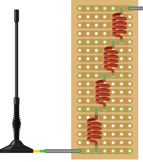
- Pitch Antenna Circuit
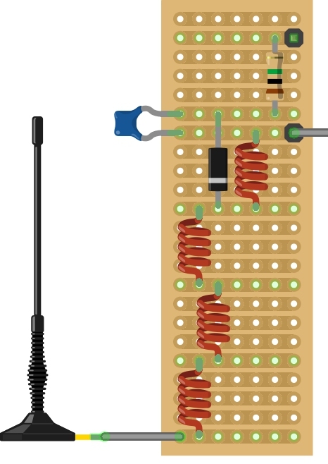
- Volume Antenna Circuit
- Variable Pitch Oscillator - Fixed Pitch Oscillator - Pitch Tuning
- Volume Oscillator - Volume Tuning
- Detector - Voltage Controlled Amplifier - VCA Processor
Photos
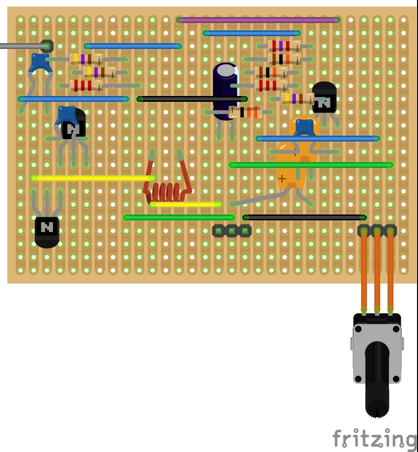
Fritzing
Actual construction resulted in difference between the fritzing layout and actual build.


