Micro-Laser Cutter Project
From a Challenge, the Project is Born
When LVL1 was discussing the purchase of a Laser Cutter, one of its members said "I could build one before you get around to buying one." And so the race began. Then on 7/13/2011, the Micro-Laser Cutter was demonstrated. On 7/14/2011, the purchased laser cutter arrived. So, the member built a laser cutter faster than the space could buy one.
The Mechanism and the Rest
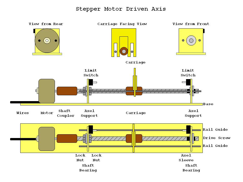
- The mechanical core of the project is the axis movement. Movement is driven by stepper motors and threaded rod with a threaded spacer. The spacer has a perfboard piece mounted with guide rail slots called a carrier. The carrier moves along the threaded rod and activates limit switches.
The threadeds rod is mounted in small bearings for smooth movement. One end locks the bearings inplace with two nuts while the other end is press-fit over a rubber tube on the threaded rod end. The stepper motor and threaded rod are coupled with a threaded spacer, shrink wrap tubing and some crazy glue. The axle supports are held in place by dual row header pins.
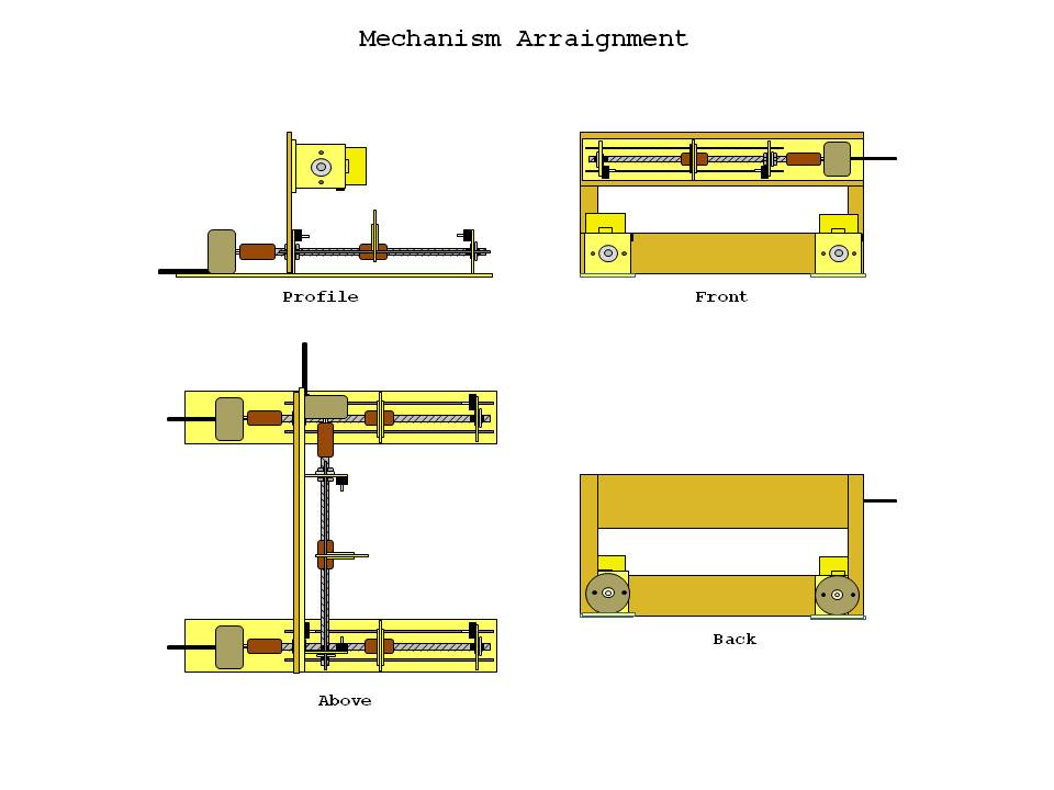
- Although the device only moves in two axes, three drive axis are employed. One stepper motor for X-Axis movement and two for Y-Axis movement.
The two Y-Axis assemblies hold a platform for the item to be laser cut.
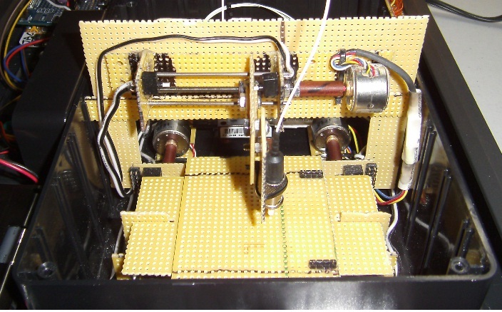
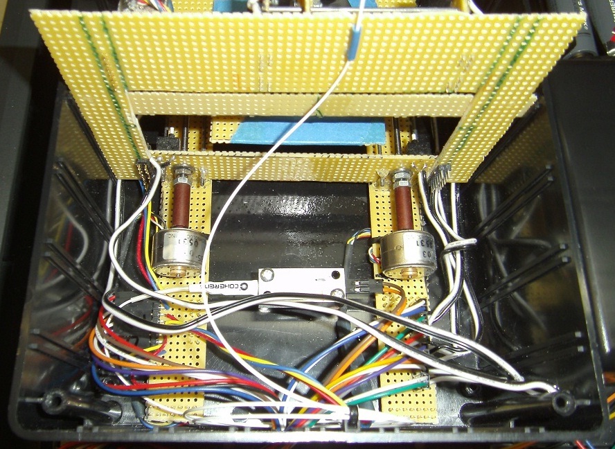
- Here are images of the assembled unit.
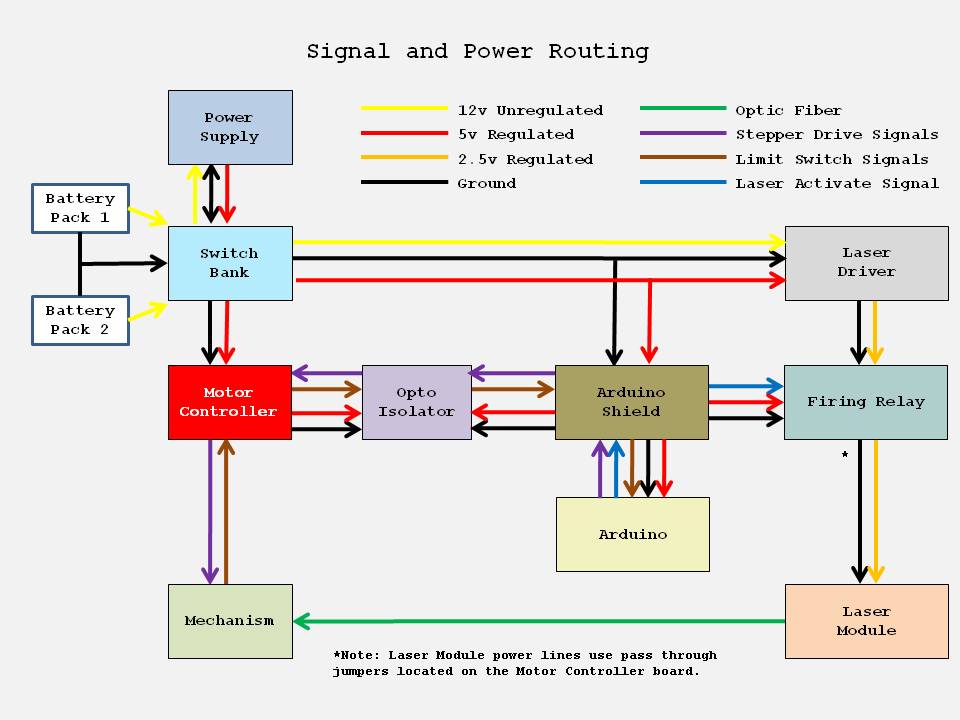
- The functional breakdown of the unit is displayed below.
The arrows show the direction of communication and power source. This particular setup does not have a single integrated power supply. Instead, one battery pack supplies power to everything except the laser, which has its own battery pack.
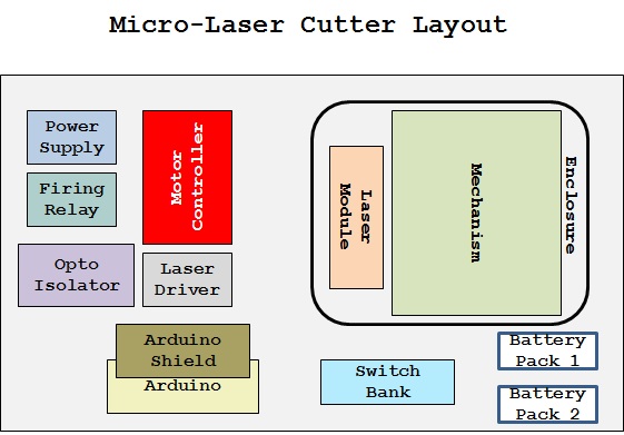
- The actual layout is displayed below.
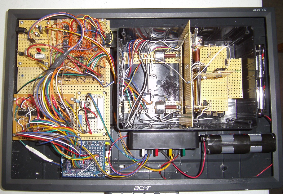
The components are arranged in/on the back panel of a flat screen monitor that was available.
From this image it is obvious that perfboard plays a major structural part in the unit.
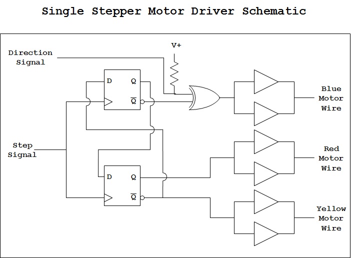
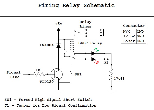
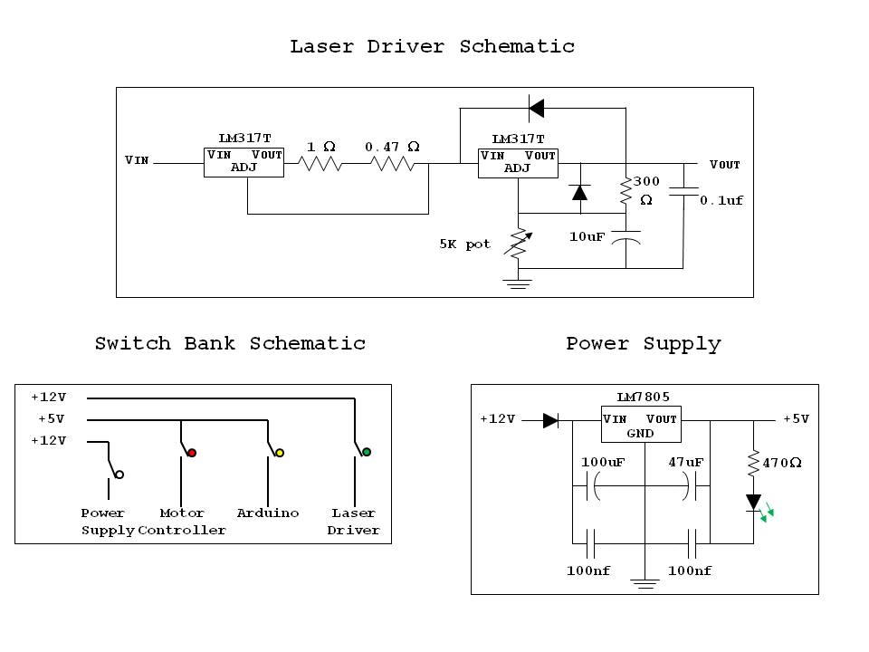
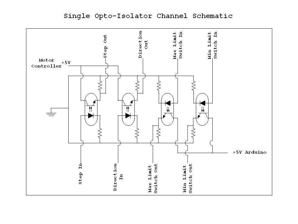
- And here are the circuits.
This is a truncation of the circuit provided by Goldmine electronics with the stepper mototrs. Critical to this circuit is the grounding and connection of signal lines. Many hours were spent debugging odd behavior that was solved by not letting lines float.
This circuit is a savaged component from a testing fixture used on the WhiteStar Trans-Atlantic Balloon Project (also at LVL1). This circuit uses a relay to switch the power on and off to the cutting laser.
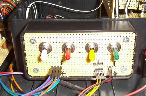
These three circuits are the power subsystems. One supplies a changable voltage and current limited supply to the cutting laser. One supplies the regulated 5 volts to the logic circuit and arduino. The final circuit is a switch bank used to activate subsystems seperately.
Because this unit is a small CNC machine with motors, an opto-isolation circuit is included to shield the electronics from motor noise. The limit switches from the axes are also isolated through this circuit.
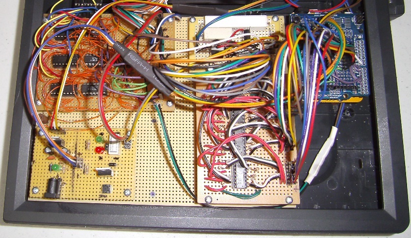
When combined, the electronic confusion of boards and wires looks like this.
The switches used to power seperate subsystems is shown here.
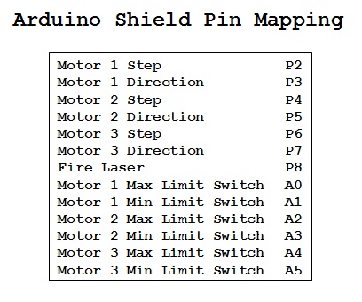
And finally, the unit uses an arduino (328). The list shows the I/O pin assignments.
So what about the software? Well, that was not a detailed part. Basically, the unit had to cut a square in a piece of plastic to win the chanllenge. The software consisted of the axes being driven to an initial start position and then repeating a square pattern until the plastic was cut through. It wasn't fancy but it did the trick.
For those thinking this is the end, here is a teaser. A second cutter is being developed. This cutter will allow the user to select an image from a touch-screen and have it cut/burned onto a plastic blank the size of a credit card. It is on the way and will have its software posted. So, stay tuned for the MK2 Micro Laser Cutter to be built and posted at the LVL1 wiki.
Thank You. JAC_101
