Magic 8 of Hearts
Introduction
WARNING LiPo battery in this project was underrated and got hot and puffed up. Use a higher rated battery.
This write up is about a project merging the Magic 8-Ball with Valentine candies. The basic premise is that the heart is shaken like a Magic 8-Ball and message reminiscent of the candy heart sayings appear in the window.
The Magic 8 of Hearts, as we call it, has several features:
1. Inductively charged.
2. Shake to activate.
3. Digital LCD display of message.
4. Magnetic reed switch to reset nano arduino
5. Magnetic reed switch to disable power to arduino while charging.
Ridiculous Backstory
LVL1 Director of Legal Evil Emeritus was acting oddly human the last few days. When asked about his behavior, he said he was preoccupied with hacking a heart. Immediately people stepped aside and a few members checked to see if they had any new chest scars. But the scare was short lived as he revealed what the heart hacking was: The Magic 8 of Hearts
Components
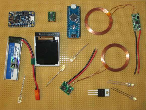
This project consists of the following parts.
| Arduino Nano | PowerBoost 500 Charger - Rechargeable 5V Lipo USB Boost @ 500mA+ |
| White LEDs | Inductive Charging Set - 5V @ 500mA max |
| 1.44" 128*128 TFT LCD SPI | 3.7v 650mah Li-po Battery |
| MMA7361LC 3-Axis Accelerometer ±1.5/6g | FQP30N06L MOSFET |
| Perf Board | Split Heart |
| Not Shown | |
| 49 ohms resister (LED) | 150 ohms resister (LCD Backlight) |
| Reed Switch | 12k ohms resister (MOSFET Limiter) |
Prepare The Heart
Make a hole in the heart.
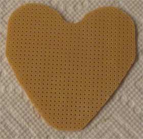
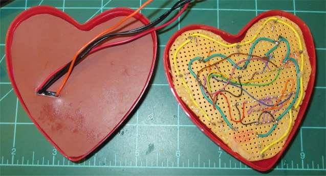
Make a insertable Perf Board
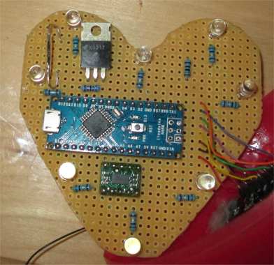
Layout the Board
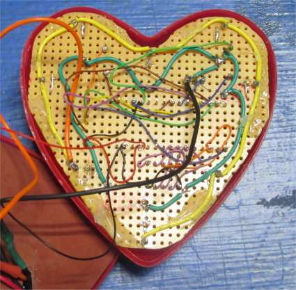
After several tries, the components are placed on the board.
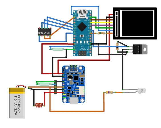
Wiring of Boards
| Arduino Nano Pin | Accelerometer Pin |
| A1 | X-Axis |
| A2 | Y-Axis |
| A3 | Z-Axis |
| A4 | Free Fall 0g |
| 3.3v | Sensitivity |
| 3.3v | Vdd |
| GND | GND |
A reed switch (N.O.) connects Arduino Reset to GND.
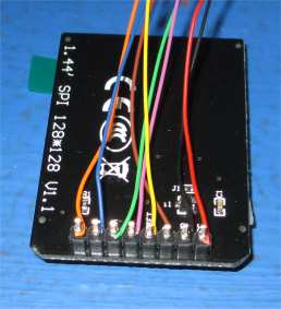
| Arduino Nano Pin | 128*128 TFT LCD SPI Pin |
| D5 | LED Backlight w/ 150 ohm resistor |
| D8 | A0 |
| D9 | Reset |
| D10 | CS |
| D11 | SDA |
| D13 | SCK |
| 3.3v | Vdd |
| GND | GND |
| Adafruit Boost Charger Pin | Other Component Pin |
| USB | Vdd Adafruit Inductive Charger |
| BAT | V+ 3.7V LiPo Battery |
| 5V Arduino Nano 5V | |
| GND | Adafruit Inductive Charger |
| GND | GND Arduino Nano |
A reed switch (N.O.) connects Charger EN to GND.
Five white LEDs with a 49 ohm resistors in series are wired in parallel. The positive rail is attached to the 3.7v line of the LiPo battery. The GND rail is attached to the MOSFET Drain lead. The MOSFET Source lead is attached to Battery GND. A 12k ohm resistor is attached across the MOSFET Gate and Source leads. The Gate lead is also attached to the Arduino D6 pin.
The coil in the picture above is a simplified representation of the inductive charging coil and associated circuitry.
Prepare the Screen
Classical wirewrap will connect the screen to the controller.
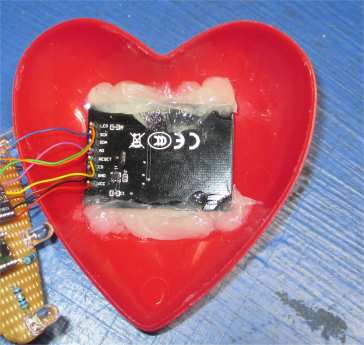
The screen is then glued into the front shell.
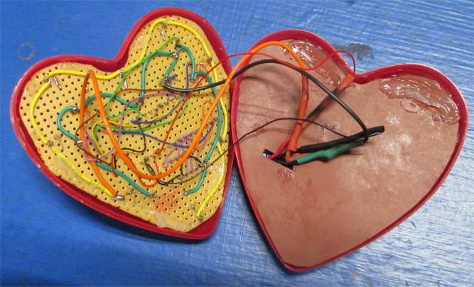
Solder up all the parts.
Power Plant
Place inductive charger receiver in back half of heart shell and glue in place.
Yes, I forgot to take a photo!
Place a rubber flap over unit to prevent shorts.
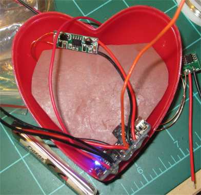
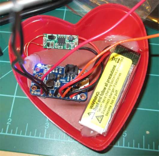
Arrange remaining power supply components.
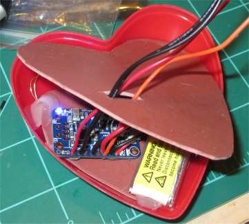
Prepare another flap to insulate the power supply from the rest of the project.
