Lightning Detector
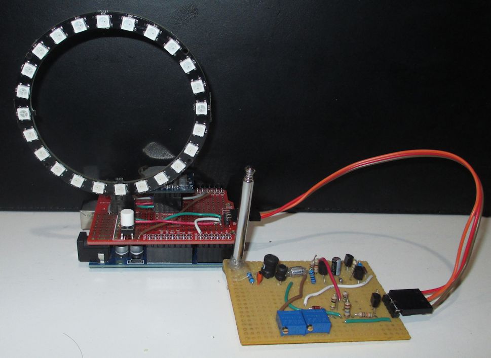
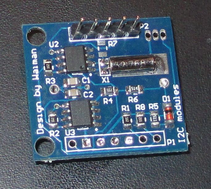
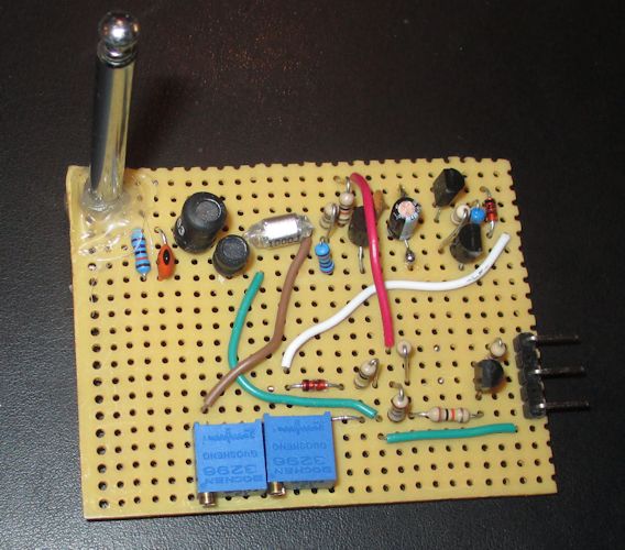
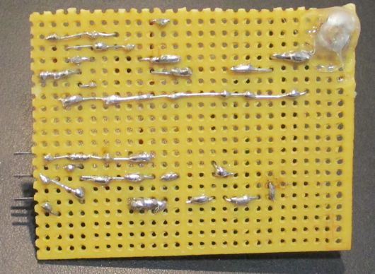
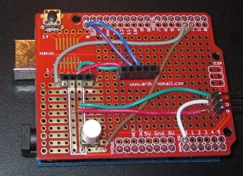
It is often in the pursuit of one project that leads one to build others. For example, let us say that the work of Victor Frankenstein was being prepared for duplication at the premier Louisville, KY hackerspace; LVL1. Instead of pursuing special wiring and fuse boxes from the landlord and LG&E, this LVL1 were to go old school and rely on the weapons of Zeus. Detecting the approaching wrath of the pagan abomination would be necessary to time the re-expression of Dr. Frankenstein's genius. With the readily available Lightning Detection Modules with multiple built in functions, commencing Victor's opus would be easy, if not too easy. And so, with an eye on sanctity and purity of the ultimate goal, they have decided to build a simple circuit attributed to Charles Wenzel and condemn the modern modules. The basic working principle is a 300kHz tank circuit with antenna. Lightning strikes induce a oscillation which is detected and amplified into a pulse. An arduino then measures the analog voltage of the generated pulse, displays a simple magnitude indicator and increments a counter. The device uses a loop of Neopixel LEDs to display the count. Added to the circuit is a Real Time Clock module which also displays the time on the loop.
Contents
Update/Correction/Crow
Later in this writeup there is a correction. The problem was in the adjustment potentiometer which is now disconnected.
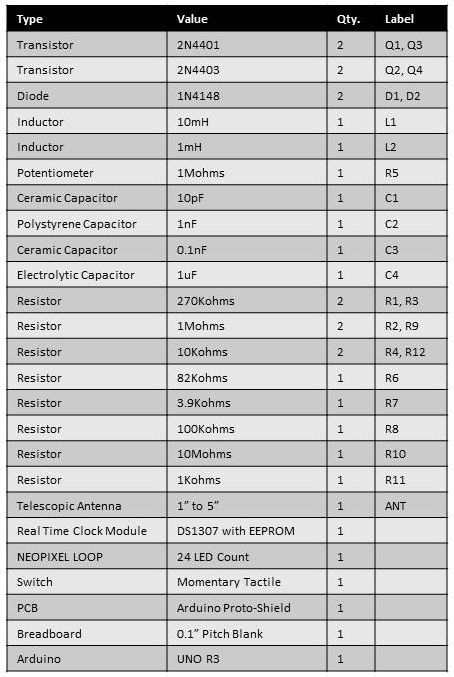
Bill of Materials
Schematic
Uncorrected Schematic Below. Show your work and acknowledge your mistakes.

Circuit Notes
As stated earlier, this circuit is based upon a circuit by Charles Wenzel (schematic below). The circuit consists of a detector and signal conditioner. The detection circuit consists of the first three transistors from left to right. The next transistor is for the signal conditioning. The signal conditioning circuit is a modification to an amp meter addon (schematic below) often paired with the detection circuit. The amp meter circuit uses a capacitor , that are not on this variant, to extended the meter's reading. Since this project uses an arduino to record the signal, extending the meter reading is not needed and only the initial signal spike is used to record the event.
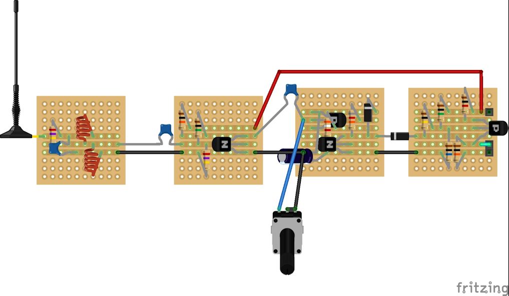
Fritzing
Arduino Wiring
Builds
Displaying Information
Recording Zeus's fury
Upon detection of a strike, the loop lights up, engulfing the loop according to the magnitude of the signal created in fading BLUE.
Reading the Device
The white momentary tactile switch is used to display the time and number of lightning strikes.
Telling Time
Time is displayed with RED and Green LED colors. There are 24 LEDs in the loop. The hour is displayed with three RED LEDs around the loop corresponding to a twelve hour clock face. The minute is mapped around the loop like a minute hand but approximated to 24 positions on the loop.
Lightning Strike Count
The top 13 LEDs represent the binary count of lightning strikes since power on, reset or 8192 strike reset. The LEDs are read from right to left in binary with RED for zero and Green for one. To ensure there is no confusion with the time display, a single WHITE LED is displayed at the bottom of the loop.
Video
Operation Observations
The device is very sensitive, too sensitive.
Among the things seen:
- Detection flash when applying power
- Detection flash when touching antenna
- Detection flash when pressing the display button
- Detection flash when underside of arduino and/or detector placed and moved on some surfaces
Mitigating options:
- Code in a wait state that clears the detection count
- Code in an setup sequence with display to let user know when it starts
- Place device in a container, keep in mind electrostatic issues
- Don't handle the antenna when in operation
- Remote display button alternative, preferably laser based because, LASERS
There is an adjustment potentiometer. But what does it do?
There are examples of Wenzel's schematic with and without the adjustment potentiometer. So I ran through the circuit and noticed that the unit I wired up was wrong. I attached the potentiometer to the first transistor base instead of the second transistor base. I then corrected the circuit and it persistently registered a signal. I cut the potentiometer from the circuit and it performed as it had before. Too sensitive, but now it does nothing. If you built the circuit from the old schematic then "CUT THE BROWN WIRE".
Code
#include <Adafruit_NeoPixel.h>
// Date and time functions using a DS1307 RTC connected via I2C and Wire lib
#include "RTClib.h"
#define Loop_NeoPixel_Pin 3
#define LOOPPIXELS 24 // Popular NeoPixel ring size
#define L_Pin A0
#define BUTTON_PIN 2
Adafruit_NeoPixel Loop_pixels(LOOPPIXELS, Loop_NeoPixel_Pin, NEO_GRB + NEO_KHZ800);
RTC_DS1307 rtc;
char daysOfTheWeek[7][12] = {"Sunday", "Monday", "Tuesday", "Wednesday", "Thursday", "Friday", "Saturday"};
long Global_Count = 0;
void setup()
{
 // put your setup code here, to run once:
 Serial.begin(9600);
 pinMode(BUTTON_PIN,INPUT_PULLUP);
 if (! rtc.begin())
   Serial.println("Couldn't find RTC");
 Loop_pixels.begin(); // INITIALIZE NeoPixel strip object (REQUIRED)
 Loop_pixels.clear(); // Set all pixel colors to 'off'
 Loop_pixels.show();            // Turn OFF all pixels ASAP
 Loop_pixels.setBrightness(50); // Set BRIGHTNESS to about 1/5 (max = 255)
}
void displayClock()
{
 int hourTime = 0;
 int AMPM = 0;
 int minuteTime = 0;
 int secondTime = 0;

 DateTime now = rtc.now();
 Loop_pixels.clear(); // Set all pixel colors to 'off'
 hourTime = now.hour();
 if (hourTime > 13)
   {
     AMPM = 1;
     hourTime = hourTime - 12;
   }
 hourTime = hourTime + 6;
 if (hourTime > 12)
   hourTime = hourTime - 12;
 if (hourTime > 11)
   hourTime = 0;
 Loop_pixels.setPixelColor((hourTime *2), Loop_pixels.Color(255, 0, 0));
 Loop_pixels.setPixelColor((hourTime *2)+1, Loop_pixels.Color(255, 0, 0));
 if (hourTime == 0)
   hourTime = 12;
 Loop_pixels.setPixelColor((hourTime *2)-1, Loop_pixels.Color(255, 0, 0));
 minuteTime = now.minute();
 minuteTime = map(minuteTime,0,59,0,23);
 minuteTime = minuteTime + 12;
 if (minuteTime > 23)
   minuteTime = minuteTime - 24;
 Loop_pixels.setPixelColor(minuteTime, Loop_pixels.Color(0, 255, 0));
 Loop_pixels.show();
 delay(5000);
 Loop_pixels.clear();
 Loop_pixels.show();
}
void displayCount(long count)
{
 int pos_1,pos_2,pos_3,pos_4,pos_5,pos_6;
 int tempCount;
 int tempDigit;
 int red_part, green_part, blue_part;
 tempCount = count;
 for(int x=0;x<13;++x)
   {
      tempDigit = tempCount % 2;
      tempCount = tempCount / 2;
      switch(tempDigit)
        {
         case 0:
           red_part = 255;
           green_part = 0;
           blue_part = 0;
           break;
         case 1:
           red_part = 0;
           green_part = 255;
           blue_part = 0;
           break;
        }
      Loop_pixels.setPixelColor(18 - x, Loop_pixels.Color(red_part, green_part, blue_part));
   }
 Loop_pixels.setPixelColor(0, Loop_pixels.Color(255,255,255));
 Loop_pixels.show(); // Set all pixel colors to 'off'
 delay(5000);
 Loop_pixels.clear();
 Loop_pixels.show();
}
void loop_neopixel_update(int magnitude_value)
{
  int red_part, green_part, blue_part;
  int magnitude_adjusted = 0;
  int power = 0;

  power = map(magnitude_value,0,1024,0,255);
  Loop_pixels.clear(); // Set all pixel colors to 'off'
  magnitude_adjusted = map(magnitude_value,0,925,1,23);
  for(int i=0; i<magnitude_adjusted; i++)
    { // For each pixel...
      red_part = 0;
      green_part = 0;
      blue_part = power;
      Loop_pixels.setPixelColor(i, Loop_pixels.Color(red_part, green_part, blue_part));
    }
  Loop_pixels.show();
}
void loop()
{
 int prev = 0;
 int present = 0;
 while (1)
   {
     present = analogRead(L_Pin);
     if (present > prev + 50)
       ++ Global_Count;
     if (Global_Count > 8191)
       Global_Count = 1;
     prev = present;
     loop_neopixel_update(present);
     if(!digitalRead(BUTTON_PIN))
       {
         displayClock();
         displayCount(Global_Count);
       }
     delay(10);
   }
}
Addition to code:
void displayCountDown()
{
 for(int x = 0; x<11; ++x)
   {
     for(int y = 0; y < LOOPPIXELS; ++y)
       {
         Loop_pixels.setPixelColor(y, Loop_pixels.Color(255 - (x*20), 255  - (x*20), 255  - (x*20)));
         Loop_pixels.show();
         delay(20);
       }
     delay(100);
   }
}
Add this to the beginning of the "loop()" function.
