Difference between revisions of "Zenbot 1216 CNC"
(→Pictures: Added spindle motor mount holes picutre) |
(→Log of research (newest to oldest): Added pictures of spindle belt groves) |
||
| Line 49: | Line 49: | ||
---- | ---- | ||
Oct 26 2012 - Mike L | Oct 26 2012 - Mike L | ||
| + | [[File:Diameter of belt grove on motor side of spindle (zenbot).jpg|thumb|Diameter of belt grove on motor side]] | ||
| + | [[File:Diameter of belt grove on spindle side (zenbot).jpg|thumb|Diameter of belt grove on spindle]] | ||
| + | [[File:Distance spindle grove to motor grove (zenbot).jpg|thumb|Distance grove to grove]] | ||
Zenbot has been moved to a desk in the front (broadway facing door) room. | Zenbot has been moved to a desk in the front (broadway facing door) room. | ||
| Line 62: | Line 65: | ||
Also critically important, all the axis are '''WAY''' out of scale. Moving the head 1.4 inches in the controlling software really moves the head very rapidly 10 inches in real space. Given the machine only has 10-20 inches of travel on x and y this makes a really easy to crash the head into the end of the rails its mounted on. Given the machine has no sensors for the end of the rails, if the software commands it there it will simply slam the head into the rails and grind the motors trying to keep moving on. (specifically moving 10" in real space read 1.3892" on the software, moving the head 10" on the y axis in real space read as 1.3762" on the software, z wasn't measured) | Also critically important, all the axis are '''WAY''' out of scale. Moving the head 1.4 inches in the controlling software really moves the head very rapidly 10 inches in real space. Given the machine only has 10-20 inches of travel on x and y this makes a really easy to crash the head into the end of the rails its mounted on. Given the machine has no sensors for the end of the rails, if the software commands it there it will simply slam the head into the rails and grind the motors trying to keep moving on. (specifically moving 10" in real space read 1.3892" on the software, moving the head 10" on the y axis in real space read as 1.3762" on the software, z wasn't measured) | ||
| − | + | To the right are pictures of measurements of the spindle belt groves, with the goal of computing what size belt we need to acquire | |
| − | |||
| − | |||
-- | -- | ||
| Line 79: | Line 80: | ||
---- | ---- | ||
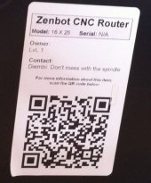
| + | [[File:QR_code_on_zenbot_as_of_Oct_2012.JPG|thumb|upright=0.56|QR code label on the side of the Zenbot]] | ||
Oct 24 2012 - Mike L | Oct 24 2012 - Mike L | ||
| − | Warped photo of the QR code that attached to the Zenbot | + | Warped photo of the QR code that attached to the Zenbot |
| − | |||
---- | ---- | ||
Oct 23 2012 - Mike L | Oct 23 2012 - Mike L | ||
Revision as of 16:58, 28 October 2012
[Equipment|Back to list of Equipment]]

|
Contents
General
|
Current status
As of Oct 24 2012 LVL1 hasn't ever been able to cut anything with this CNC. Effectively its still in the initial setup phase.
Gerrit and Mike L have been researching with the goal of getting it working. (The X,Y, & Z have previously been tested, the spindle is hasn't every been brought online)
Equipment Description
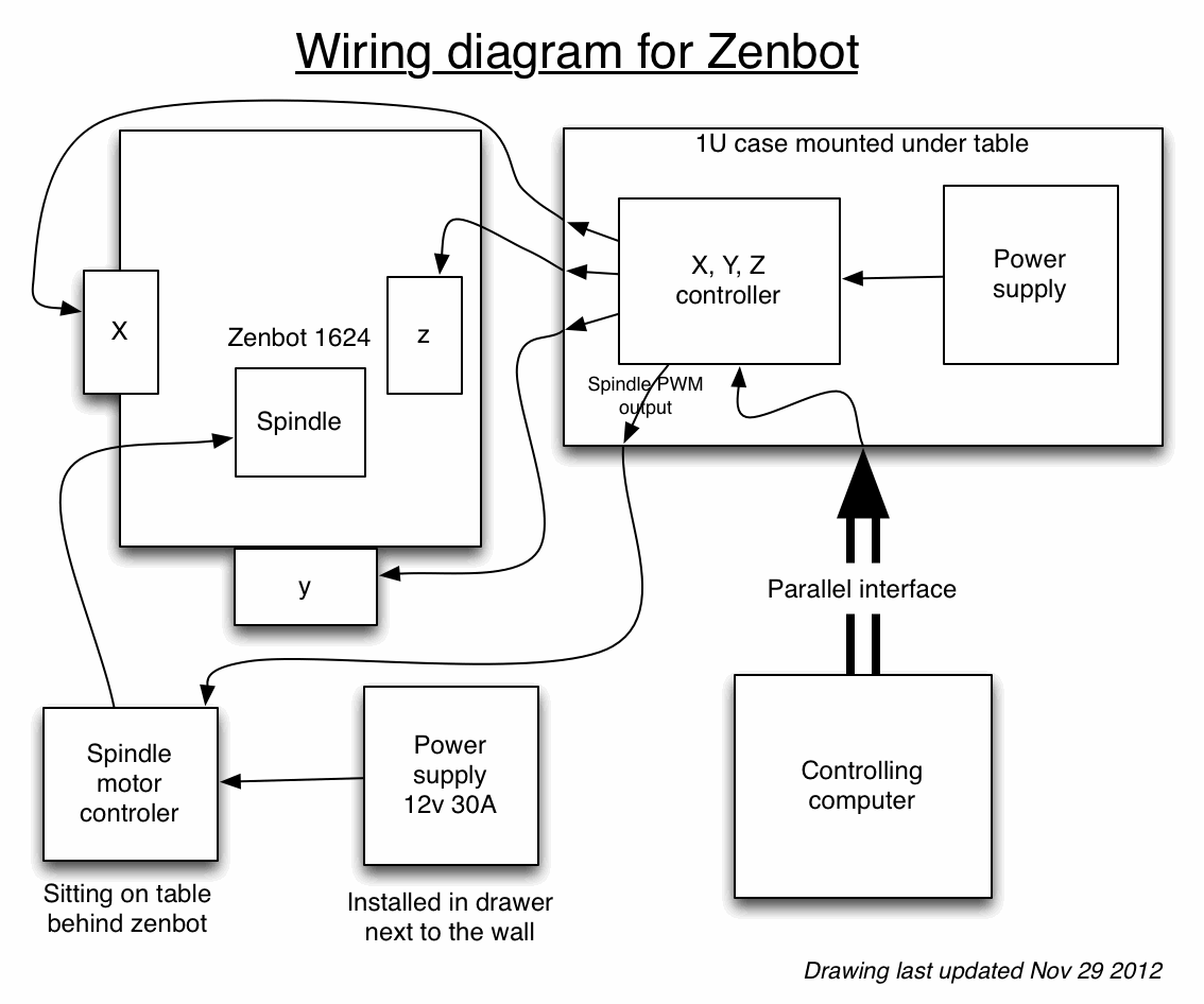
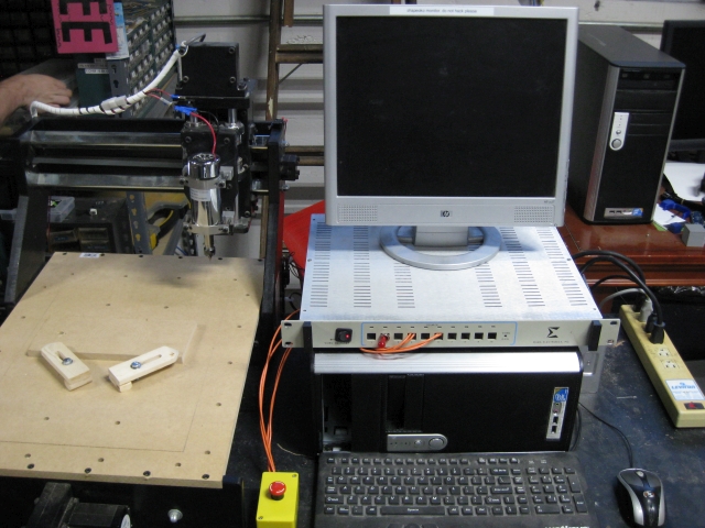
Parts that make up this system:
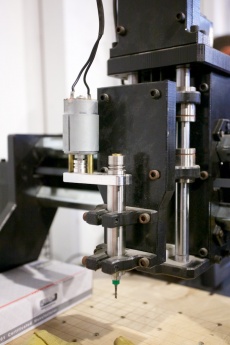
- Zenbot itself (Includes the body, armatures, and the x, y, and z motors and actuation hardware (belts))
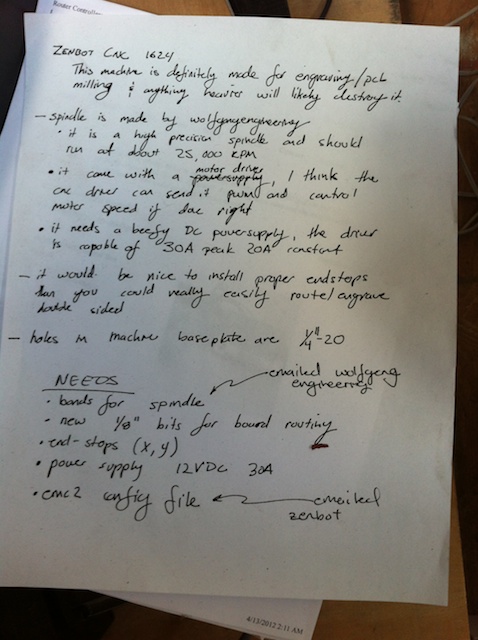
- Believed to be a Zenbot 1624, hasn't been absolutely confirmed (Unsure if zenbot stamps model numbers on their products) zenbot 1624 product page
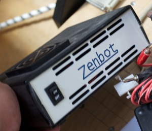
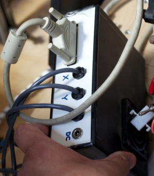
- X, Y, Z motor controller
- Believed to be a Mechatronics 3-axis CNC micro-stepper motor driver mechtronics 3-axis
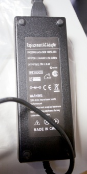
- Power brick for X, Y, Z controller
- Labeled "PA3290U-2ACA SEB 100P2-15.0". Input 100-240v 2.5A 50/60Hz. Output 19V at 6.3A. Center of connector is plus, outer shield is minus.
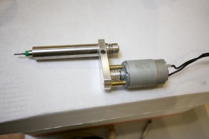
- Spindle (the routing part) - Believed to be a Wolfgang Engineering ... um ... spindle? (they don't seem to have any model info on the spindle or historical information on the website)
- Wolfgang engineering website
- The belts needed to couple the motor to the spindle are MISSING.
- Gerrit has talked with Wolfgang about this and he may have enough info to order the belts as parts (They may effectively be big O-rings)
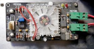
- Spindle motor controller
- Cytron Technologies MD30B
- Spindle power supply - MISSING
- Documentation for the MD30B controller says that it wants between 10 and 30Vdc with with a peak (output) of 30A (at 12Vdc?). Current product from wolfgangengineering has 200W 12Vdc motor, so 30A peek seems possible.
- Computer running EMC2 CNC control software and that has a parallel port
- Thin dell desktop sitting with the zenbot is believed to be ready to go. There is some debate whether the EMC2 configure is complete. The people with Zenbot have said they have a (non-guaranteed) config that a customer made for EMC2 but thus far they haven't posted or emailed it to us
- Bits
- There is one bit with the Zenbot, but to be of use more will have to be acquired. There seems to be agreement that the best way is to buy of Ebay, more digging will be needed to understand what to buy and how to re-cert/re-measure it in order to make it usable with the machine.
Pictures
Operating instructions
As-of-Oct-2012 the equipment shouldn't be operated
Notes from initial equipment build
Log of research (newest to oldest)
Oct 26 2012 - Mike L
Zenbot has been moved to a desk in the front (broadway facing door) room.
It is missing one of the rubber feet (that might have been added aftermarket). May be easiest to just replace all four - the three that are still on are clearly "stick on" type. There is no special size or shape required.
PC originally wouldn't boot. Chris P. futzed with the ram in the machine (added/removed/cleaned-with-eraser) and the machine became willing to boot.
Once machine was booting the EMC2/linuxcnc?/axis-software was willing to run, and upon turning on the X,Y,Z controller, the software would drive the armature.
The machine is sitting with its orignal QR code facing out, this seem to be a good way point it so-as to have the x driver-motor pointing out at the user as it slides left to right BUT the config on the machine currently has both x and y configured for the machine rotated 180 degrees. I'm working to understand the config, with the expectation that I'm going to reverse both the x and the y (the z is fine)
Also critically important, all the axis are WAY out of scale. Moving the head 1.4 inches in the controlling software really moves the head very rapidly 10 inches in real space. Given the machine only has 10-20 inches of travel on x and y this makes a really easy to crash the head into the end of the rails its mounted on. Given the machine has no sensors for the end of the rails, if the software commands it there it will simply slam the head into the rails and grind the motors trying to keep moving on. (specifically moving 10" in real space read 1.3892" on the software, moving the head 10" on the y axis in real space read as 1.3762" on the software, z wasn't measured)
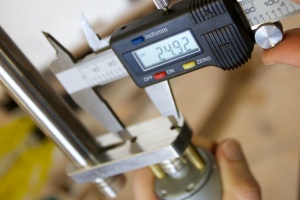
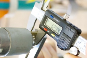
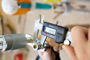
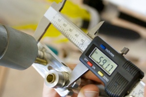
To the right are pictures of measurements of the spindle belt groves, with the goal of computing what size belt we need to acquire
--
Chris Pettus did some googling and found another zenbot user using a Wolfgang spindle and powering it with a computer power supply: https://plus.google.com/103014027224354212001/posts/9EELxYozG4W
Oct 25 2012 - Mike L
In a back-and-forth with Chorgy he said: "The spindle I ran using a generic 13v regulated bench top that I bought from radio shack for like $30-$40." Which I'm somewhat unclear if he donated but regardless is not in the pile of equipment with the Zenbot.
Chorgy also added that he really can't see the motor drawing more then 20A 12v dc max (.. through the motor controller board) and so he though a computer power supply would work.
Oct 24 2012 - Mike L
Warped photo of the QR code that attached to the Zenbot
Oct 23 2012 - Mike L
Following up on what I found out about the zenbot:
- Chris connected me to Gerrit, he is the writer of the note (that I sent earlier) on the zenbot and seems to be on top of what needs to be done to get it going. (I.E. he does "have the ball")
- Current status
- Believed capable of high precision operation other then a non-operating spindle (the router part) because of multiple missing parts, and likely incompletely configured control software.
- Parts needed to get the zenbot operating:
- Power supply for the spindle motor
- either found by chorgy or an expense of $75-150
- Belts for spindle
- Gerrit had an exchange with Wolfgang Eng (maker of the spindle part) and thinks he may have enough info to order from a parts house (price currently unknown, though expected to be low)
- More bits (there is one with the zenbot now)
- Both Gerrit and chorgy agree that ebay is the way to go. Gerrit's comment was that the reason that ebay bits are so cheap is because they are partly used and have become slightly out of dimensional spec. With effort, the bits can be re-measure there-by enabling them to be used at full precision.
- Config for EMC2? (x,y,z stepper motor control software)
- The current assumption is that the EMC2 on the linux box doesn't have a fully configured config for the zenbot. Gerrit has contacted the zenbot and they have said they will send him a (customer supplied) EMC2 config, though they haven't yet so he is planning on bugging them again.
- Brian W posted that he had x,y,z working a few months back, Brian if you think the config is complete then please reply so Gerrit doesn't have to keep hassling the zenbot folks
- Power supply for the spindle motor
If the zenbot gets up and running, there are number of improvement that Gerrit is already thinking about ("stops" to calibrate the arms - likely requiring a different controller, enclosure for the control systems, vacuum system, etc..)
The consensus seems to be that machine is in good shape, and should really be capable of high accuracy milling if the parts/config are done and the machine is treated gently.
I have some extra time over the next few weeks and I'm going to try and help Gerrit move things forward, I suspect that may not be enough to get the system operational, but if nothing else I'll make sure to document what happens.
Pre Oct 20 2012
Had written notes from Gerrit:

