Difference between revisions of "Lightning Detector"
| Line 25: | Line 25: | ||
==Lightning Strike Count== | ==Lightning Strike Count== | ||
The top 13 LEDs represent the binary count of lightning strikes since power on, reset or 8192 strike reset. The LEDs are read from right to left in binary with RED for zero and Green for one. To ensure there is no confusion with the time display, a single WHITE LED is displayed at the bottom of the loop. | The top 13 LEDs represent the binary count of lightning strikes since power on, reset or 8192 strike reset. The LEDs are read from right to left in binary with RED for zero and Green for one. To ensure there is no confusion with the time display, a single WHITE LED is displayed at the bottom of the loop. | ||
| + | =Code= | ||
| + | <code> | ||
| + | </code> | ||
Revision as of 08:41, 26 August 2021
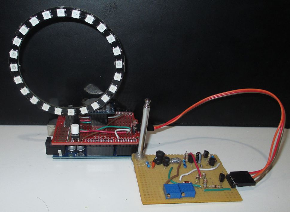
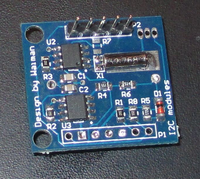
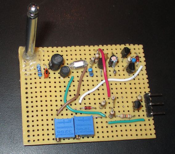
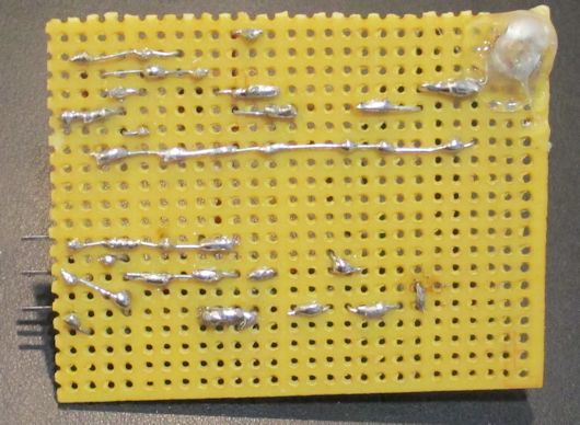
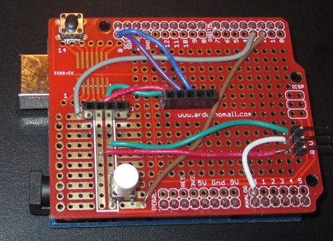
With the readily available Lightning Detection Modules with multiple built in functions, I decided to build a simple circuit attributed to Charles Wenzel. The basic working principle is a 300kHz tank circuit with antenna. Lightning strikes induce a oscillation which is detected and amplified into a pulse. The arduino then measures the analog voltage of the generated pulse and increments a counter. The device uses a loop of Neopixel LEDs to display the count. Added to the circuit is a RTC which also displays the time on the loop.
Contents
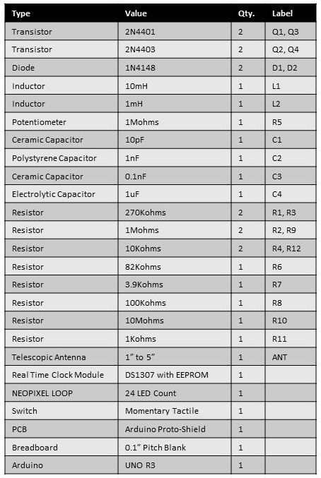
Bill of Materials
Schematic
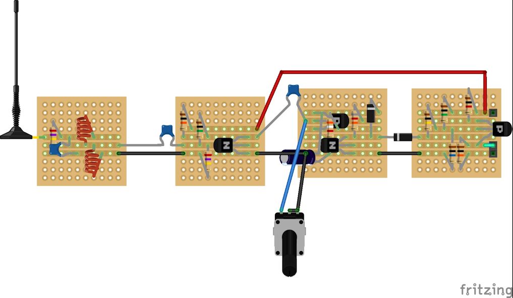
Fritzing
Builds
Displaying Information
The white momentary tactile switch is used to display the time and number of lightning strikes.
Telling Time
Time is displayed with RED and Green LED colors. There are 24 LEDs in the loop. The hour is displayed with three RED LEDs around the loop corresponding to a twelve hour clock face. The minute is mapped around the loop like a minute hand but approximated to 24 positions on the loop.
Lightning Strike Count
The top 13 LEDs represent the binary count of lightning strikes since power on, reset or 8192 strike reset. The LEDs are read from right to left in binary with RED for zero and Green for one. To ensure there is no confusion with the time display, a single WHITE LED is displayed at the bottom of the loop.
Code
